FIT STANDARD / ADJUSTMENT METHOD ADJUSTMENT
-
INSPECT HOOD SUB-ASSEMBLY
-
Check that the clearance measurements of areas a through f are within each standard range.
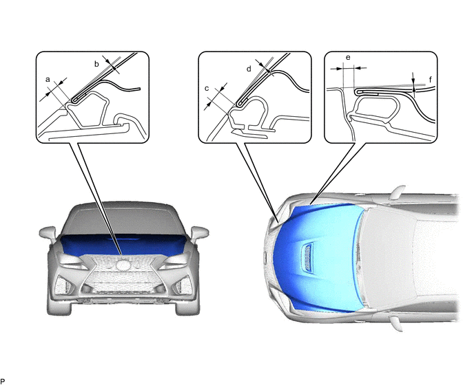
Standard Clearance Area Measurement Area Measurement a 1.85 to 5.85 mm (0.0728 to 0.230 in.) b -1.85 to 2.15 mm (-0.0728 to 0.0846 in.) c 3.45 to 7.45 mm (0.136 to 0.293 in.) d -2.05 to 1.95 mm (-0.0807 to 0.0768 in.) e 2.2 to 5.2 mm (0.0866 to 0.205 in.) f -1.5 to 1.5 mm (-0.0591 to 0.0591 in.)
-
-
ADJUST HOOD SUB-ASSEMBLY
-
Horizontally and vertically adjust the hood.
-
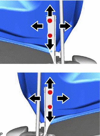
Loosen the 4 hinge bolts of the hood.
-
Adjust the clearance between the hood and front fender by moving the hood.
-
Tighten the 4 hinge bolts after adjustment.
- Torque:
- 13 N*m { 133 kgf*cm, 10 ft.*lbf }
-
-
Adjust the height of the front end of the hood using the hood bumper cushions.
-
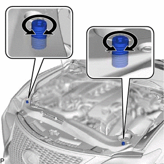
Adjust the 2 hood bumper cushions so that the heights of the hood and fenders are aligned.
Tech Tips
Raise or lower the front end of the hood by turning the 2 hood bumper cushions.
-
-
Adjust the hood lock.
-
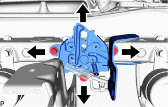
Loosen the 3 bolts.
-
Adjust the hood lock and tighten the 3 bolts.
- Torque:
- 7.5 N*m { 76 kgf*cm, 66 in.*lbf }
-
Check that the striker can engage the hood lock smoothly.
-
-
-
INSPECT FRONT DOOR
-
Check that the clearance measurements of areas a through h are within each standard range.
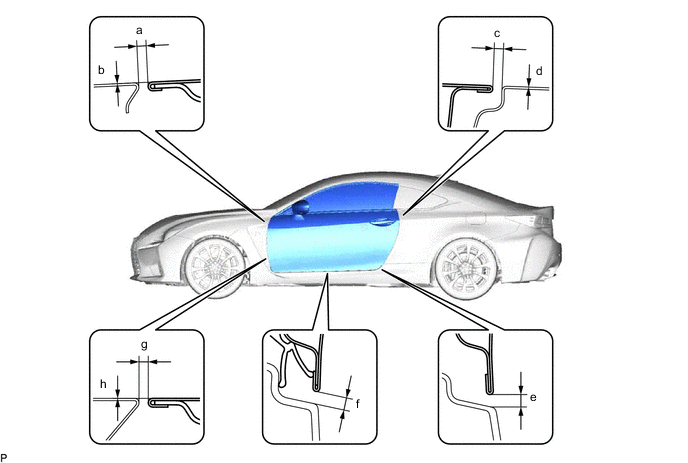
Standard Clearance Area Measurement Area Measurement a 2.3 to 5.3 mm (0.0906 to 0.209 in.) b -1.5 to 1.5 mm (-0.0591 to 0.0591 in.) c 2.3 to 5.3 mm (0.0906 to 0.209 in.) d -1.5 to 1.5 mm (-0.0591 to 0.0591 in.) e 3.65 to 6.65 mm (0.144 to 0.262 in.) f 3.65 to 6.65 mm (0.144 to 0.262 in.) g 2.3 to 5.3 mm (0.0906 to 0.209 in.) h -1.5 to 1.5 mm (-0.0591 to 0.0591 in.)
-
-
ADJUST FRONT DOOR
Note
Make sure to turn the engine switch off when adjusting the door lock striker.
-
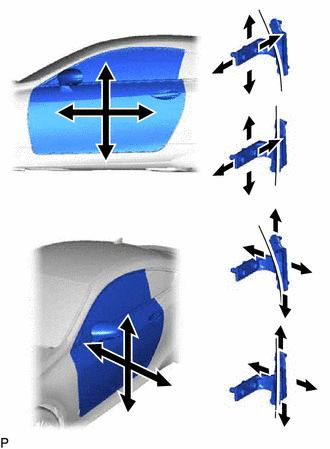
Using SST, loosen the 2 hinge bolts on the vehicle body and adjust the door position.
- SST
- 09812-00010
-
Tighten the 2 hinge bolts on the vehicle body after adjustment.
- Torque:
- 32.5 N*m { 331 kgf*cm, 24 ft.*lbf }
-
Loosen the 2 hinge bolts on the door and adjust the door position.
-
Tighten the 2 hinge bolts on the door after adjustment.
- Torque:
- 32.5 N*m { 331 kgf*cm, 24 ft.*lbf }
-
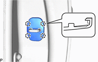
Disengage the 4 claws and remove the front door lock striker cover.
-
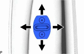
Using a T40 "TORX" socket wrench, slightly loosen the 2 striker mounting screws.
-
Using a brass bar and a hammer, hit the striker to adjust its position.
-
Using a T40 "TORX" socket wrench, tighten the 2 striker mounting screws after adjustment.
- Torque:
- 23 N*m { 235 kgf*cm, 17 ft.*lbf }
-
Engage the 4 claws to install the front door lock striker cover.
-
-
INSPECT LUGGAGE COMPARTMENT DOOR
-
Check that the clearance measurements of areas a through d are within each standard range.
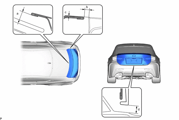
Standard Clearance Area Measurement Area Measurement a 8.0 mm (0.315 in.) b 2.0 to 5.0 mm (0.0787 to 0.197 in.) c -1.5 to 1.5 mm (-0.0591 to 0.0591 in.) d 5.2 to 9.2 mm (0.205 to 0.362 in.)
-
-
ADJUST LUGGAGE COMPARTMENT DOOR
-
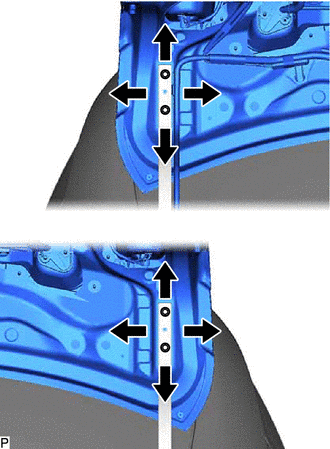
Loosen the 4 door side hinge bolts to adjust the door horizontally and vertically.
-
Tighten the 4 bolts after adjustment.
- Torque:
- 8.0 N*m { 82 kgf*cm, 71 in.*lbf }
-
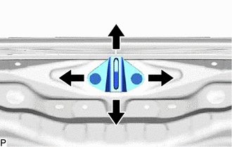
Using a T40 "TORX" socket wrench, slightly loosen the 2 striker mounting screws.
-
Using a brass bar and a hammer, hit the striker to adjust its position.
-
Using a T40 "TORX" socket wrench, tighten the 2 striker mounting screws after adjustment.
- Torque:
- 23 N*m { 235 kgf*cm, 17 ft.*lbf }
-