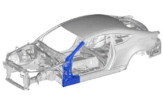
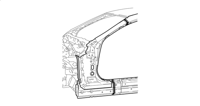
FRONT BODY PILLAR CUT AND JOIN REPLACEMENT SECTIONS
-
With the cowl top side upper panel assembly and front body pillar lower gusset assembly removed.
-
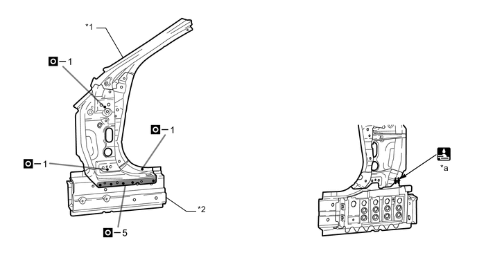
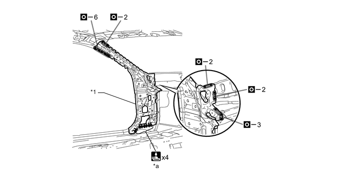
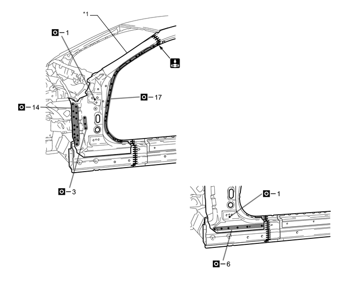
REMOVAL
Symbol Meaning 
Remove Weld Points 
Remove Weld Points 
Remove Weld Points 
Cut with Disc Sander etc. 
Cut and Join Location 
Cut Location for Supply Parts
-
A is reused.
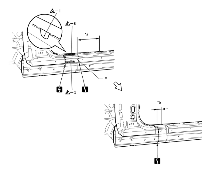
*a 290 mm (11.42 in.) *b 60 mm (2.36 in.) 
Laser Screw Welding - - 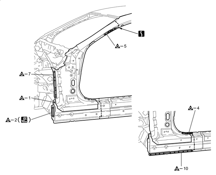
Laser Screw Welding - - -
Roughly cut open the panel so that the adhesive can be reached. Cut through the adhesive with a cut chisel to remove the panel.
Tech Tips
In cases where the adhesive cannot be removed with a cut chisel, heat the adhesive with an industrial heater gun or gas burner taking care not to cause panel deformation by overheating.

Adhesive - - 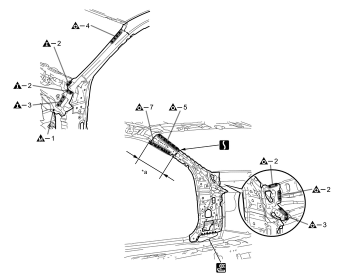
*a 280 mm (11.02 in.) - - Laser Screw Welding - - 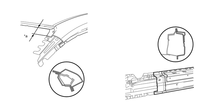
*a 70 mm (2.76 in.) - -
-
-
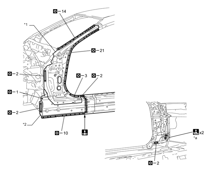
INSTALLATION
Symbol Meaning 
Plug Weld 
Plug Weld 
Plug Weld Cut and Join Location 
Fillet Weld 
Butt Weld
-
Inspect the fitting of the related parts around the new parts before welding. This affects the appearance of the finish.
-
Temporarily install the new parts and measure each part of the new parts in accordance with the body dimension diagram. (See the body dimensions)
-
If the entire supply part is not needed, remove the part of the supply part that is needed.
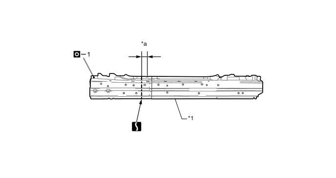
*1 ROCKER PANEL SUB-ASSEMBLY OUTER - - *a 60 mm (2.36 in.) - - -
Apply adhesive (3MTMAutomixTMPanel Bonding Adhesive #8115).
Tech Tips
-
Apply a light coat of adhesive around the plug welding points.
-
Apply enough adhesive to the panels.
Adhesive - - -
-
Before temporarily installing the new parts, weld the front body pillar reinforce sub-assembly upper and rocker panel sub-assembly outer with the standard number of welding points.
*1 FRONT BODY PILLAR REINFORCE SUB-ASSEMBLY UPPER *2 ROCKER PANEL SUB-ASSEMBLY OUTER *a 15 mm (0.59 in.) - - -
Weld the front body pillar sub-assembly inner to the vehicle side.
*1 FRONT BODY PILLAR SUB-ASSEMBLY INNER - - *a 15 mm (0.59 in.) - - Laser Screw Welding - - -
Apply adhesive (3MTMAutomixTMPanel Bonding Adhesive #8115).
Tech Tips
-
Apply a light coat of adhesive around the plug welding points.
-
Apply enough adhesive to the panels.
Adhesive - - -
-
Weld the front body pillar reinforce sub-assembly upper and rocker panel sub-assembly outer to the vehicle side.
*1 FRONT BODY PILLAR REINFORCE SUB-ASSEMBLY UPPER *2 ROCKER PANEL SUB-ASSEMBLY OUTER *a 15 mm (0.59 in.) - - Laser Screw Welding - - -
Apply adhesive (3MTMAutomixTMPanel Bonding Adhesive #8115).
Tech Tips
-
Apply a light coat of adhesive around the plug welding points.
-
Apply enough adhesive to the panels.
Adhesive - - -
-
Weld the front body pillar outer to the vehicle side.
*1 FRONT BODY PILLAR OUTER - - 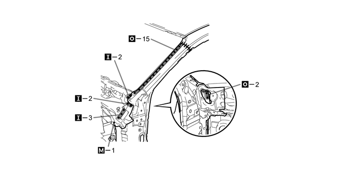
-
Weld the A to the vehicle side.
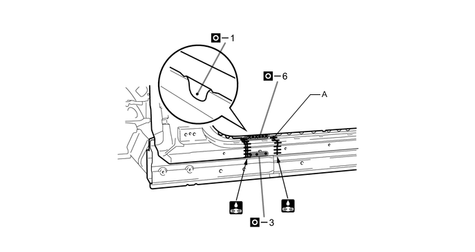
-
After welding, apply the foamed sealing material to the corresponding parts. (See the painting /coating)
-
After welding, apply body sealer to the corresponding parts. (See the painting /coating)
-
After applying the top coat, apply anti-rust agent to the internal panel portion of the closed section structural weld points.
-