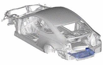
REAR FLOOR PAN ASSEMBLY REPLACEMENT
-
With the body lower back panel assembly removed.
-
REMOVAL
Symbol Meaning 
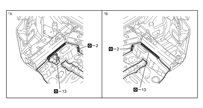
Remove Weld Points 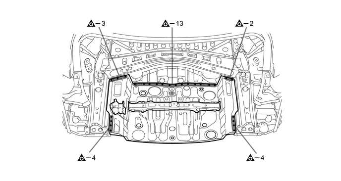
*A LH Side *B RH Side
-
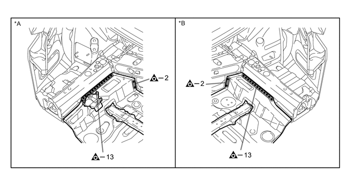
Roughly cut open the panel so that the adhesive can be reached. Cut through the adhesive with a cut chisel to remove the panel.
Tech Tips
In cases where the adhesive cannot be removed with a cut chisel, heat the adhesive with an industrial heater gun or gas burner taking care not to cause panel deformation by overheating.

Adhesive - -
-
-
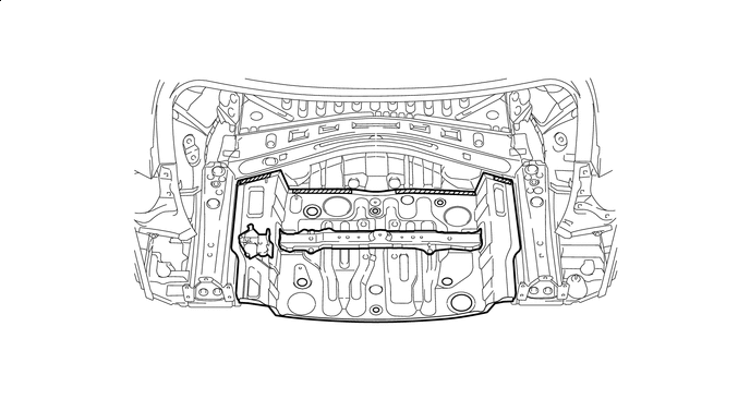
INSTALLATION
Symbol Meaning 
Plug Weld 
Plug Weld 
Plug Weld 
Fillet Weld
-
Before temporarily installing the new parts, weld the rear floor pan, rear floor crossmember bracket sub-assembly, jack carrier assembly and weld bolts with the standard number of welding points.
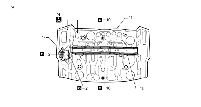
*A Upper Face - - *1 REAR FLOOR PAN *2 REAR FLOOR CROSSMEMBER BRACKET SUB-ASSEMBLY *3 JACK CARRIER ASSEMBLY *4 WELD BOLTS -
Before temporarily installing the new parts, weld the rear floor pan and weld bolts with the standard number of welding points.
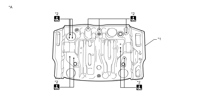
*A Lower Face - - *1 REAR FLOOR PAN *2 WELD BOLTS -
Apply adhesive (3MTMAutomixTMPanel Bonding Adhesive #8115).
Tech Tips
-
Apply a light coat of adhesive around the plug welding points.
-
Apply enough adhesive to the panels.
Adhesive - - 
*A LH Side *B RH Side -
-
After welding, apply body sealer and undercoating to the corresponding parts. (See the painting/coating)
-
After applying the top coat, apply anti-rust agent to the internal panel portion of the closed section structural weld points.
-