FIT STANDARD / ADJUSTMENT METHOD ADJUSTMENT
-
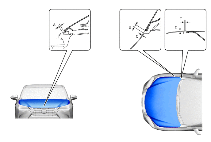
INSPECT HOOD SUB-ASSEMBLY
-
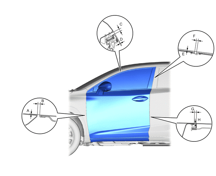
Check that the clearance measurements of areas A to E are within the standard ranges.
-
-
ADJUST HOOD SUB-ASSEMBLY
-
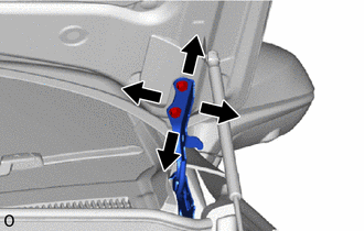
Adjust the hood position.
-
Loosen the 4 hinge bolts on the hood and adjust the hood position.
-
Move the hood and adjust the clearance between the hood and front fender.
-
Tighten the 4 hinge bolts on the hood after the adjustment.
- Torque:
- 13 N*m { 133 kgf*cm, 9.6 ft.*lbf }
-
-
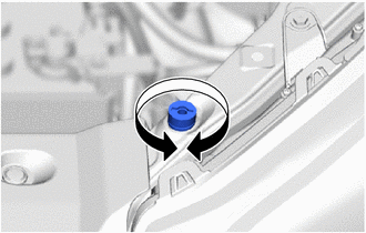
Adjust the cushion rubber so that the hood and fender are aligned.
Tech Tips
Raise or lower the front end of the hood by turning the cushion rubber.
-
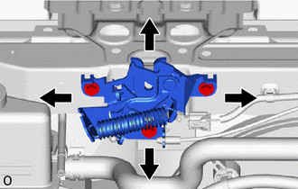
Adjust the hood lock.
-
Loosen the 3 bolts.
-
Adjust the hood lock position so that the striker can enter it smoothly.
-
Tighten the 3 bolts after the adjustment.
- Torque:
- 8.0 N*m { 82 kgf*cm, 71 in.*lbf }
-
-
-
INSPECT FRONT DOOR PANEL SUB-ASSEMBLY
-
Check that the clearance measurements of areas A to L are within the standard ranges.
-
-
ADJUST FRONT DOOR PANEL SUB-ASSEMBLY
-
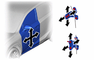
Using SST, loosen the hinge bolts on the body and adjust the door position.
- SST
- 09812-00010
-
Tighten the hinge bolts on the body after the adjustment.
- Torque:
- 26 N*m { 265 kgf*cm, 19 ft.*lbf }
-
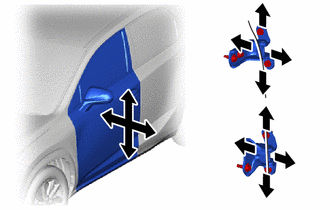
Loosen the hinge bolts on the door and adjust the door position.
-
Tighten the hinge bolts on the door after the adjustment.
- Torque:
- 26 N*m { 265 kgf*cm, 19 ft.*lbf }
-
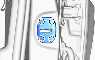
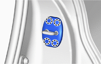
Detach the 4 claws and remove the striker cover.
-
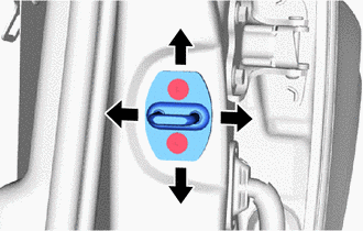
Using a T40 "TORX" socket wrench, adjust the striker position by slightly loosening the striker mounting screws and hitting the striker with a plastic-faced hammer.
- Torque:
- 23 N*m { 235 kgf*cm, 17 ft.*lbf }
-
Attach the 4 claws and install the striker cover.
-
-
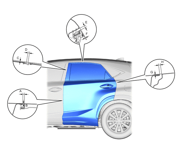
INSPECT REAR DOOR PANEL SUB-ASSEMBLY
-
Check that the clearance measurements of areas A to L are within the standard ranges.
-
-
ADJUST REAR DOOR PANEL SUB-ASSEMBLY
-
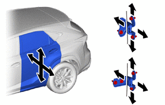
Using SST, loosen the hinge bolts on the body and adjust the door position.
- SST
- 09812-00010
-
Tighten the hinge bolts on the body after the adjustment.
- Torque:
- 26 N*m { 265 kgf*cm, 19 ft.*lbf }
-
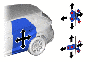
Loosen the hinge bolts on the door and adjust the door position.
-
Tighten the hinge bolts on the door after the adjustment.
- Torque:
- 26 N*m { 265 kgf*cm, 19 ft.*lbf }
-
Detach the 4 claws and remove the striker cover.
-
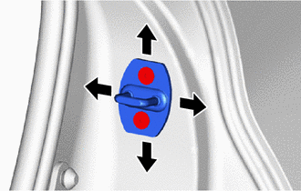
Using a T40 "TORX" socket wrench, adjust the striker position by slightly loosening the striker mounting screws and hitting the striker with a plastic-faced hammer.
- Torque:
- 23 N*m { 235 kgf*cm, 17 ft.*lbf }
-
Attach the 4 claws and install the striker cover.
-
-
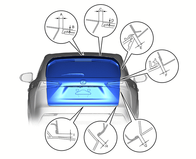
REMOVE BACK DOOR PANEL SUB-ASSEMBLY
-
Check that the clearance measurements of areas A to N are within the standard ranges.
-
-
ADJUST BACK DOOR PANEL SUB-ASSEMBLY
-
Before adjusting the upper end of the back door up and down or left and right, loosen the bolts.
-
Tighten the hinge bolts on the body after the adjustment.
- Torque:
- 15.5 N*m { 158 kgf*cm, 11 ft.*lbf }
-
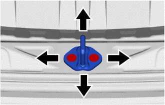
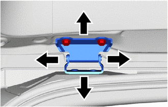
Using a T40 "TORX" socket wrench, adjust the striker position by slightly loosening the striker mounting screws and hitting the striker with a plastic-faced hammer.
-
Using a T40 "TORX" socket wrench, tighten the striker mounting screws after the adjustment.
- Torque:
- 23 N*m { 235 kgf*cm, 17 ft.*lbf }
-