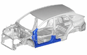
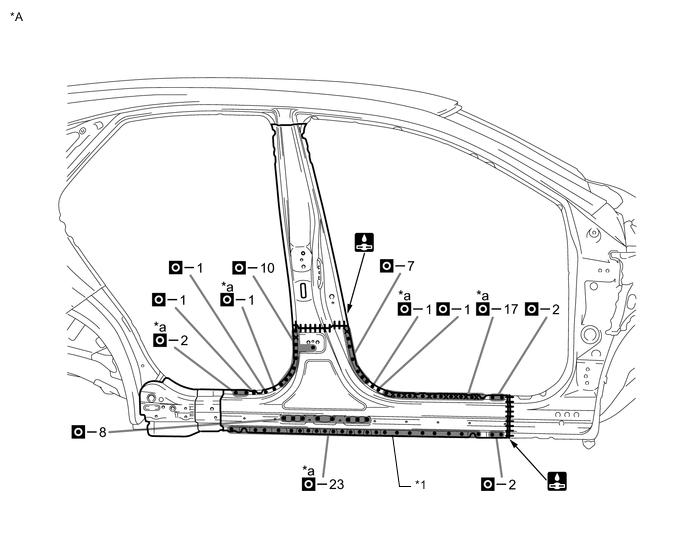
ROCKER PANEL CUT AND JOIN REPLACEMENT SECTIONS
-
With the cowl top side upper panel assembly, cowl top side panel assembly and quarter panel cut andjoin replacement sections (small areas) removed.
-
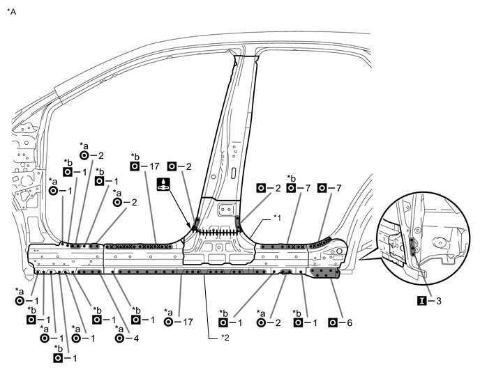
REMOVAL
Symbol Meaning 
Remove Weld Points 
Remove Weld Points 
Remove Weld Points 
Cut with Disc Sander etc. 
Cut and Join Location 
Cut Location for Supply Parts
-
Do not butt weld or heat repair because the heat decreases the strength of areas where ultra high strength steel is used. (See the introduction)
-
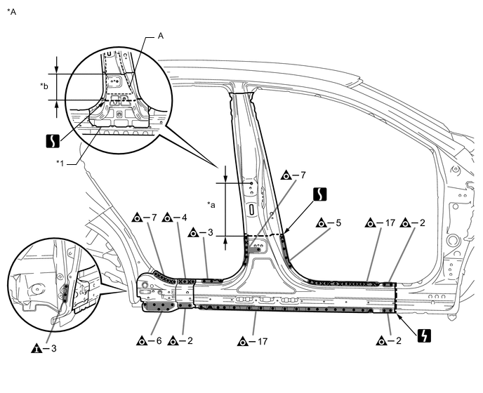
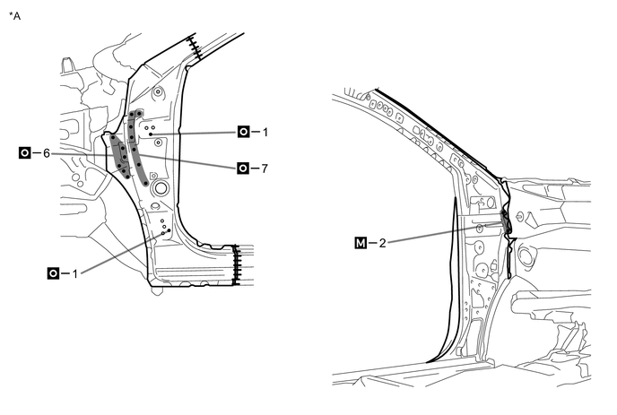
Remove the front body pillar upper outer.
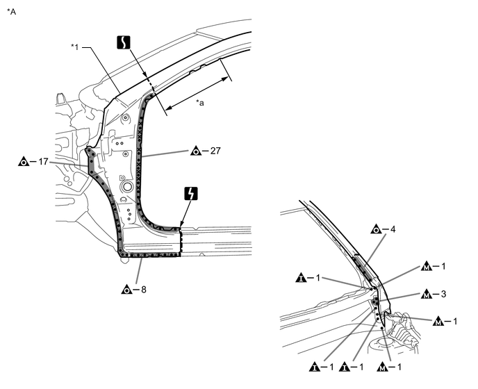
*A LH - - *1 FRONT BODY PILLAR UPPER OUTER - - *a 430 mm (16.93 in.) - - 
Laser Screw Welding - - 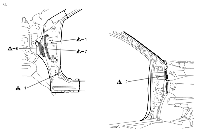
*A LH - - -
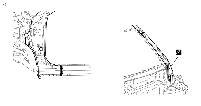
Roughly cut open the panel so that the adhesive can be reached. Cut through the adhesive with a cut chisel to remove the panel.
Tech Tips
In cases where the adhesive cannot be removed with a cut chisel, heat the adhesive with an industrial heater gun or gas burner taking care not to cause panel deformation by overheating.
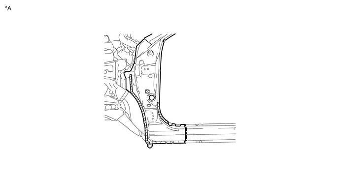
*A LH - - 
Adhesive - - -
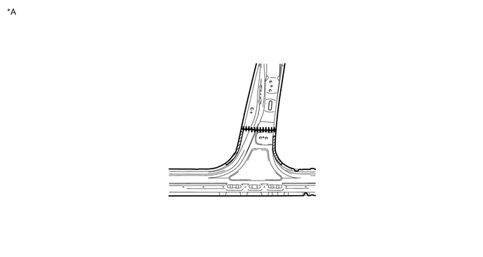
Remove the A.
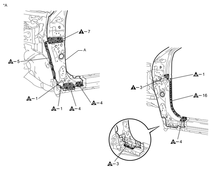
*A LH - - Laser Screw Welding - - -
Roughly cut open the panel so that the adhesive can be reached. Cut through the adhesive with a cut chisel to remove the panel.
Tech Tips
In cases where the adhesive cannot be removed with a cut chisel, heat the adhesive with an industrial heater gun or gas burner taking care not to cause panel deformation by overheating.

*A LH - - Adhesive - - -
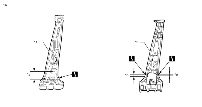
Carefully cut the center body pillar reinforcement sub-assembly so as not to damage A.
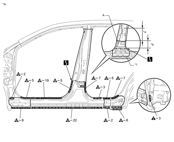
*A LH - - *1 CENTER BODY PILLAR REINFORCEMENT SUB-ASSEMBLY - - *a 290 mm (11.42 in.) *b 180 mm (7.09 in.) Laser Screw Welding - - 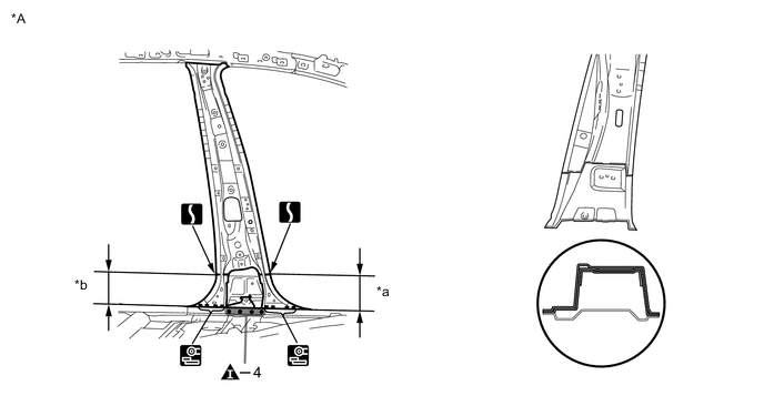
*A LH - - *a 145 mm (5.71 in.) *b 145 mm (5.71 in.) -
Roughly cut open the panel so that the adhesive can be reached. Cut through the adhesive with a cut chisel to remove the panel.
Tech Tips
In cases where the adhesive cannot be removed with a cut chisel, heat the adhesive with an industrial heater gun or gas burner taking care not to cause panel deformation by overheating.
*A LH - - Adhesive - - -
Carefully cut the center body pillar reinforcement sub-assembly so as not to damage A.
*A RH - - *1 CENTER BODY PILLAR REINFORCEMENT SUB-ASSEMBLY - - *a 290 mm (11.42 in.) *b 180 mm (7.09 in.) Laser Screw Welding - - 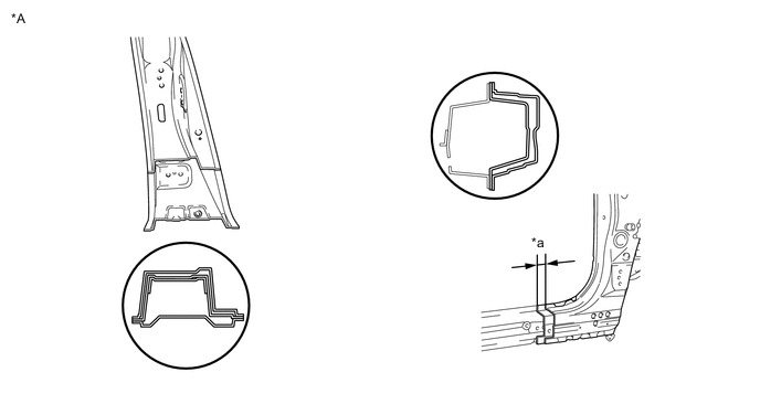
*A RH - - *a 35 mm (1.38 in.) - - 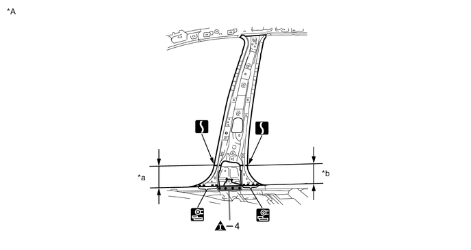
*A RH - - *a 145 mm (5.71 in.) *b 145 mm (5.71 in.) -
Roughly cut open the panel so that the adhesive can be reached. Cut through the adhesive with a cut chisel to remove the panel.
Tech Tips
In cases where the adhesive cannot be removed with a cut chisel, heat the adhesive with an industrial heater gun or gas burner taking care not to cause panel deformation by overheating.
*A RH - - Adhesive - -
-
-
INSTALLATION
Symbol Meaning Remove Weld Points 
Spot Weld 
Plug Weld 
Plug Weld 
Plug Weld Cut and Join Location 
Fillet Weld 
Butt Weld 
Body Sealer
-
Inspect the fitting of the related parts around the new parts before welding. This affects the appearance of the finish.
-
Temporarily install the new parts and measure each part of the new parts in accordance with the body dimension diagram. (See the body dimensions)
-
If the entire supply part is not needed, remove the part of the supply part that is needed.

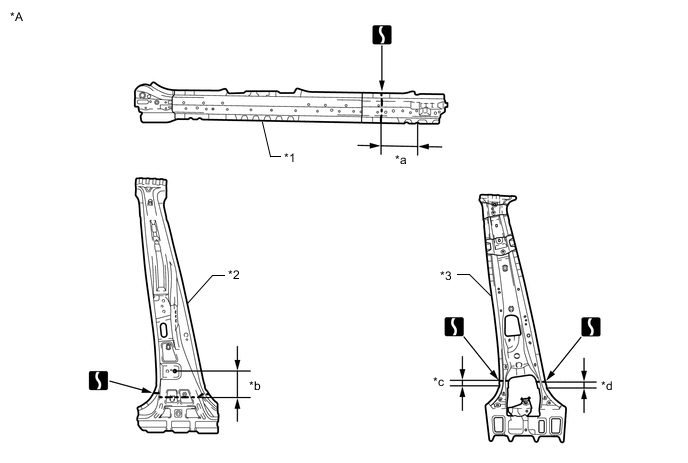
*A LH - - *1 FRONT PILLAR REINFORCEMENT SUB-ASSEMBLY LOWER - - -
If the entire supply part is not needed, remove the part of the supply part that is needed.
*A LH - - *1 CENTER BODY PILLAR REINFORCEMENT SUB-ASSEMBLY *2 CENTER BODY PILLAR SUB-ASSEMBLY INNER *a 130 mm (5.12 in.) *b 35 mm (1.38 in.) *c 30 mm (1.18 in.) - - -
Apply adhesive (3MTMAutomixTMPanel Bonding Adhesive #8115).
Tech Tips
-
Apply a light coat of adhesive around the plug welding points.
-
Apply enough adhesive to the panels.
*A LH - - Adhesive - - -
-
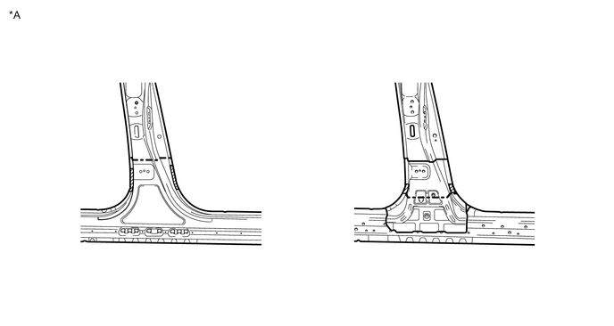
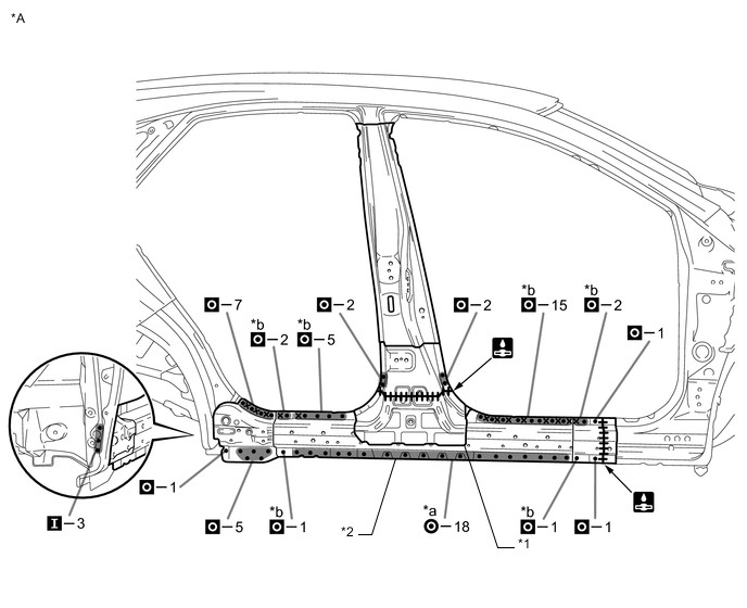
Before temporarily installing the new parts, weld the center body pillar reinforcement sub-assembly, center body pillar sub-assembly inner and rocker panel sub-assembly outer with the standard number of welding points.
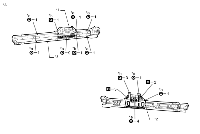
*A LH - - *1 CENTER BODY PILLAR REINFORCEMENT SUB-ASSEMBLY *2 CENTER BODY PILLAR SUB-ASSEMBLY INNER *3 ROCKER PANEL SUB-ASSEMBLY OUTER - - *a Ultra High Strength Steel Welding Point *b Ultra High Strength Steel Welding Point
-
When welding 2 panels together including 980 MPa ultra high strength steel.
*a: Spot weld Pressure 2940 N (300 kgf, 661 lbf) Weld current 10000 A Weld time 16 Cyc. (0.27 Sec.) *b: Plug weld Plug diameter 10 mm (0.39 in.) Wire type AWS A5.18 ER70S-3 Shield gas Metal active gas Note
Be sure to use Metal active gas (Ar 80% + CO220%) as the shield gas when plug welding.Sufficient weld strength cannot be assured when using 100% CO2shield gas.
Follow the welding conditions below when welding ultra high strength steel to assure sufficient weld strength. (When repairing this model)
-
-
Apply adhesive (3MTMAutomixTMPanel Bonding Adhesive #8115).
Tech Tips
-
Apply a light coat of adhesive around the plug welding points.
-
Apply enough adhesive to the panels.
*A LH - - Adhesive - - -
-
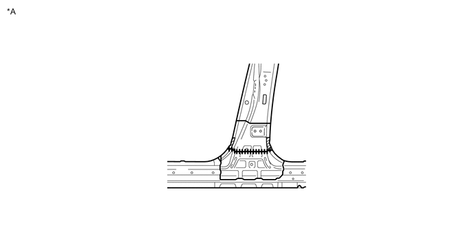
Weld the center body pillar reinforcement sub-assembly, center body pillar sub-assembly inner and rocker panel sub-assembly outer to the vehicle side.
*A LH - - *1 CENTER BODY PILLAR REINFORCEMENT SUB-ASSEMBLY *2 ROCKER PANEL SUB-ASSEMBLY OUTER *a Ultra High Strength Steel Welding Point *b Ultra High Strength Steel Welding Point Laser Screw Welding - -
-
When welding 2 panels together including 980 MPa ultra high strength steel.
*a: Spot weld Pressure 2940 N (300 kgf, 661 lbf) Weld current 10000 A Weld time 16 Cyc. (0.27 Sec.) *b: Plug weld Plug diameter 10 mm (0.39 in.) Wire type AWS A5.18 ER70S-3 Shield gas Metal active gas Note
Be sure to use Metal active gas (Ar 80% + CO220%) as the shield gas when plug welding.Sufficient weld strength cannot be assured when using 100% CO2shield gas.
Follow the welding conditions below when welding ultra high strength steel to assure sufficient weld strength. (When repairing this model)
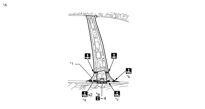
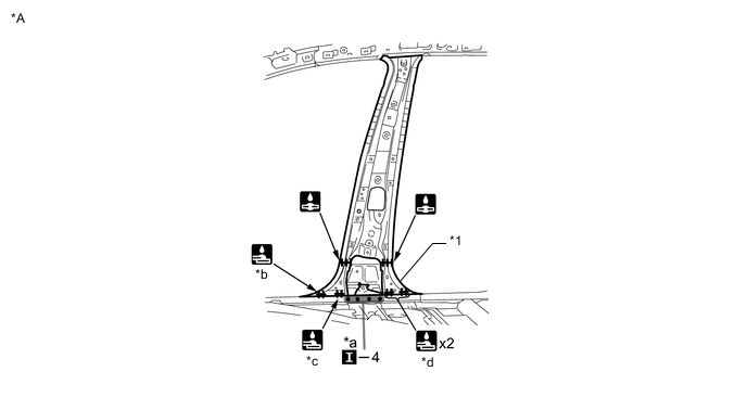
*A LH - - *1 CENTER BODY PILLAR SUB-ASSEMBLY INNER - - *a Ultra High Strength Steel Welding Point *b 15 mm (0.59 in.) *c 10 mm (0.39 in.) *d 10 mm (0.39 in.)
-
When welding more than 3 panels together including 980 MPa ultra high strength steel. (When plug welding a third panel to 2 panels which are welded under the conditions described above.)
*a: Plug weld Plug diameter Same as the standard method (See the introduction) Wire type AWS A5.18 ER70S-3 Shield gas Metal active gas Note
Be sure to use Metal active gas (Ar 80% + CO220%) as the shield gas when plug welding.Sufficient weld strength cannot be assured when using 100% CO2shield gas.
Follow the welding conditions below when welding ultra high strength steel to assure sufficient weld strength. (When repairing this model)
-
-
Apply adhesive (3MTMAutomixTMPanel Bonding Adhesive #8115).
Tech Tips
-
Apply a light coat of adhesive around the plug welding points.
-
Apply enough adhesive to the panels.
*A LH - - Adhesive - - -
-
Weld the A to the vehicle side.
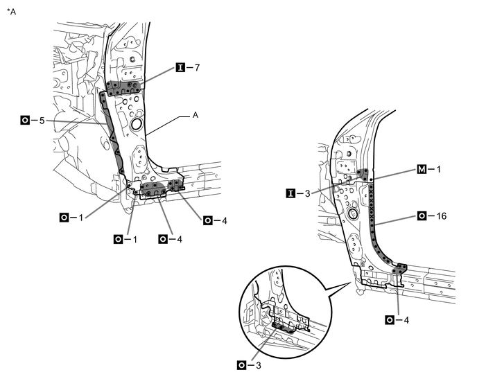
*A LH - - Laser Screw Welding - - -
Apply adhesive (3MTMAutomixTMPanel Bonding Adhesive #8115).
Tech Tips
-
Apply a light coat of adhesive around the plug welding points.
-
Apply enough adhesive to the panels.
*A LH - - Adhesive - - -
-
Weld the rocker panel outer to the vehicle side.
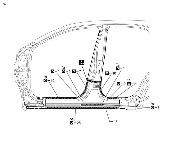
*A LH - - *1 ROCKER PANEL OUTER - - *a Ultra High Strength Steel Welding Point - - Laser Screw Welding - -
-
When welding more than 3 panels together including 980 MPa ultra high strength steel. (When plug welding a third panel to 2 panels which are welded under the conditions described above.)
*a: Plug weld Plug diameter Same as the standard method (See the introduction) Wire type AWS A5.18 ER70S-3 Shield gas Metal active gas Note
Be sure to use Metal active gas (Ar 80% + CO220%) as the shield gas when plug welding.Sufficient weld strength cannot be assured when using 100% CO2shield gas.
Follow the welding conditions below when welding ultra high strength steel to assure sufficient weld strength. (When repairing this model)
-
-
Apply adhesive (3MTMAutomixTMPanel Bonding Adhesive #8115).
Tech Tips
-
Apply a light coat of adhesive around the plug welding points.
-
Apply enough adhesive to the panels.
-
-
Before installing a new part, apply body sealer.
Tech Tips
Apply body sealer in an even, continuous bead.
*A LH - - Adhesive - - -
Weld the front body pillar upper outer to the vehicle side.
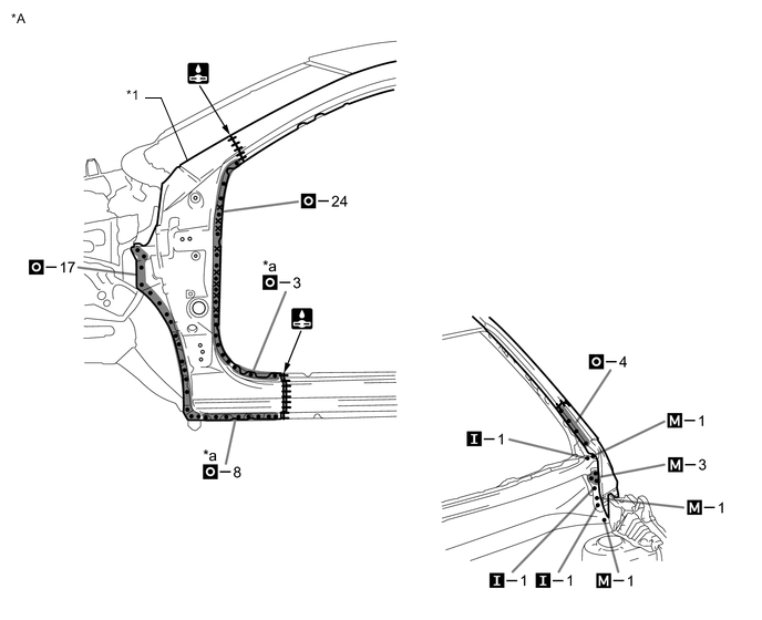
*A LH - - *1 FRONT BODY PILLAR UPPER OUTER - - *a Ultra High Strength Steel Welding Point - - Laser Screw Welding - -
-
When welding more than 3 panels together including 980 MPa ultra high strength steel. (When plug welding a third panel to 2 panels which are welded under the conditions described above.)
*a: Plug weld Plug diameter Same as the standard method (See the introduction) Wire type AWS A5.18 ER70S-3 Shield gas Metal active gas Note
Be sure to use Metal active gas (Ar 80% + CO220%) as the shield gas when plug welding.Sufficient weld strength cannot be assured when using 100% CO2shield gas.
Follow the welding conditions below when welding ultra high strength steel to assure sufficient weld strength. (When repairing this model)
*A LH - - -
-
If the entire supply part is not needed, remove the part of the supply part that is needed.
*A RH - - *1 ROCKER REINFORCE SUB-ASSEMBLY OUTER *2 CENTER BODY PILLAR REINFORCEMENT SUB-ASSEMBLY *3 CENTER BODY PILLAR SUB-ASSEMBLY INNER - - *a 200 mm (7.87 in.) *b 130 mm (5.12 in.) *c 30 mm (1.18 in.) *d 35 mm (1.38 in.) -
Apply adhesive (3MTMAutomixTMPanel Bonding Adhesive #8115).
Tech Tips
-
Apply a light coat of adhesive around the plug welding points.
-
Apply enough adhesive to the panels.
*A RH - - Adhesive - - -
-
Before temporarily installing the new parts, weld the center body pillar reinforcement sub-assembly, rocker reinforce sub-assembly outer and center body pillar sub-assembly inner with the standard number of welding points.
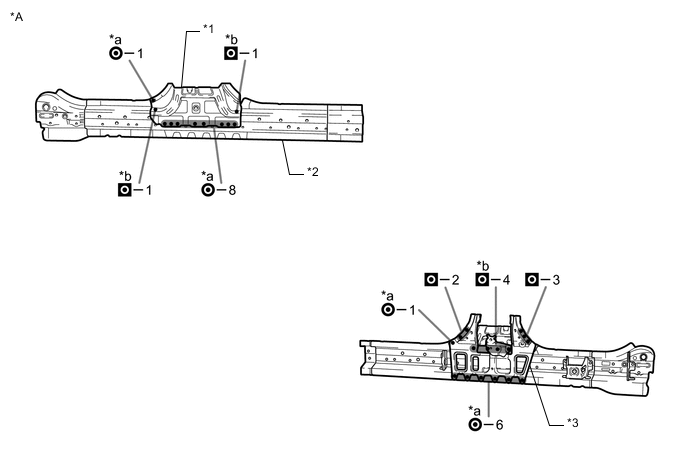
*A RH - - *1 CENTER BODY PILLAR REINFORCEMENT SUB-ASSEMBLY *2 ROCKER REINFORCE SUB-ASSEMBLY OUTER *3 CENTER BODY PILLAR SUB-ASSEMBLY INNER - - *a Ultra High Strength Steel Welding Point *b Ultra High Strength Steel Welding Point
-
When welding 2 panels together including 980 MPa ultra high strength steel.
*a: Spot weld Pressure 2940 N (300 kgf, 661 lbf) Weld current 10000 A Weld time 16 Cyc. (0.27 Sec.) *b: Plug weld Plug diameter 10 mm (0.39 in.) Wire type AWS A5.18 ER70S-3 Shield gas Metal active gas Note
Be sure to use Metal active gas (Ar 80% + CO220%) as the shield gas when plug welding.Sufficient weld strength cannot be assured when using 100% CO2shield gas.
Follow the welding conditions below when welding ultra high strength steel to assure sufficient weld strength. (When repairing this model)
-
-
Apply adhesive (3MTMAutomixTMPanel Bonding Adhesive #8115).
Tech Tips
-
Apply a light coat of adhesive around the plug welding points.
-
Apply enough adhesive to the panels.
*A RH - - Adhesive - - -
-
Weld the center body pillar reinforcement sub-assembly, center body pillar sub-assembly inner and rocker reinforce sub-assembly outer to the vehicle side.
*A RH - - *1 CENTER BODY PILLAR REINFORCEMENT SUB-ASSEMBLY *2 ROCKER REINFORCE SUB-ASSEMBLY OUTER *a Ultra High Strength Steel Welding Point *b Ultra High Strength Steel Welding Point Laser Screw Welding - -
-
When welding 2 panels together including 980 MPa ultra high strength steel.
*a: Spot weld Pressure 2940 N (300 kgf, 661 lbf) Weld current 10000 A Weld time 16 Cyc. (0.27 Sec.) *b: Plug weld Plug diameter 10 mm (0.39 in.) Wire type AWS A5.18 ER70S-3 Shield gas Metal active gas Note
Be sure to use Metal active gas (Ar 80% + CO220%) as the shield gas when plug welding.Sufficient weld strength cannot be assured when using 100% CO2shield gas.
Follow the welding conditions below when welding ultra high strength steel to assure sufficient weld strength. (When repairing this model)
*A RH - - *1 CENTER BODY PILLAR SUB-ASSEMBLY INNER - - *a Ultra High Strength Steel Welding Point *b 15 mm (0.59 in.) *c 10 mm (0.39 in.) *d 10 mm (0.39 in.)
-
When welding more than 3 panels together including 980 MPa ultra high strength steel. (When plug welding a third panel to 2 panels which are welded under the conditions described above.)
*a: Plug weld Plug diameter Same as the standard method (See the introduction) Wire type AWS A5.18 ER70S-3 Shield gas Metal active gas Note
Be sure to use Metal active gas (Ar 80% + CO220%) as the shield gas when plug welding.Sufficient weld strength cannot be assured when using 100% CO2shield gas.
Follow the welding conditions below when welding ultra high strength steel to assure sufficient weld strength. (When repairing this model)
-
-
Apply adhesive (3MTMAutomixTMPanel Bonding Adhesive #8115).
Tech Tips
-
Apply a light coat of adhesive around the plug welding points.
-
Apply enough adhesive to the panels.
*A RH - - Adhesive - - -
-
Weld the rocker panel outer to the vehicle side.
*A RH - - *1 ROCKER PANEL OUTER - - *a Ultra High Strength Steel Welding Point - - Laser Screw Welding - -
-
When welding more than 3 panels together including 980 MPa ultra high strength steel. (When plug welding a third panel to 2 panels which are welded under the conditions described above.)
*a: Plug weld Plug diameter Same as the standard method (See the introduction) Wire type AWS A5.18 ER70S-3 Shield gas Metal active gas Note
Be sure to use Metal active gas (Ar 80% + CO220%) as the shield gas when plug welding.Sufficient weld strength cannot be assured when using 100% CO2shield gas.
Follow the welding conditions below when welding ultra high strength steel to assure sufficient weld strength. (When repairing this model)
-
-
After welding, apply body sealer and undercoating to the corresponding parts. (See the painting /coating)
-
After applying the top coat, apply anti-rust agent to the internal panel portion of the closed section structural weld points.
-