REAR SUSPENSION CROSSMEMBER TWO-DIMENSIONAL DISTANCE
Tech Tips
-
Length measurements are indicated at the points where the arrows extending from the zero point intersect the lines that extend towards the outside of the illustration from each point.
-
In cases in which only one dimension is given, left and right are symmetrical.
-
For symbols, capital letters indicate right side of vehicle, small letters indicate left side of vehicle (seen from rear).
| Symbol | Name | Hole Diameter mm (in.) |
|---|---|---|
| A, a | Rear Suspension Crossmember Installation Hole | φ24 (0.94) |
| B, b | Rear Suspension Lower Arm No.1 Installation Hole | 24.1X15.2 (0.95X0.60) |
| C, c | Rear Suspension Lower Arm No.2 Installation Hole | φ12.4 (0.49) |
| D, d | Rear Suspension Crossmember Installation Hole | φ22.5 (0.89) |
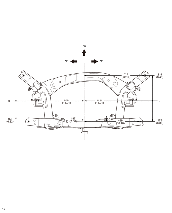
| *A | FRONT | *B | LH |
| *C | RH | - | - |
| *a | mm (in.) |
- | - |
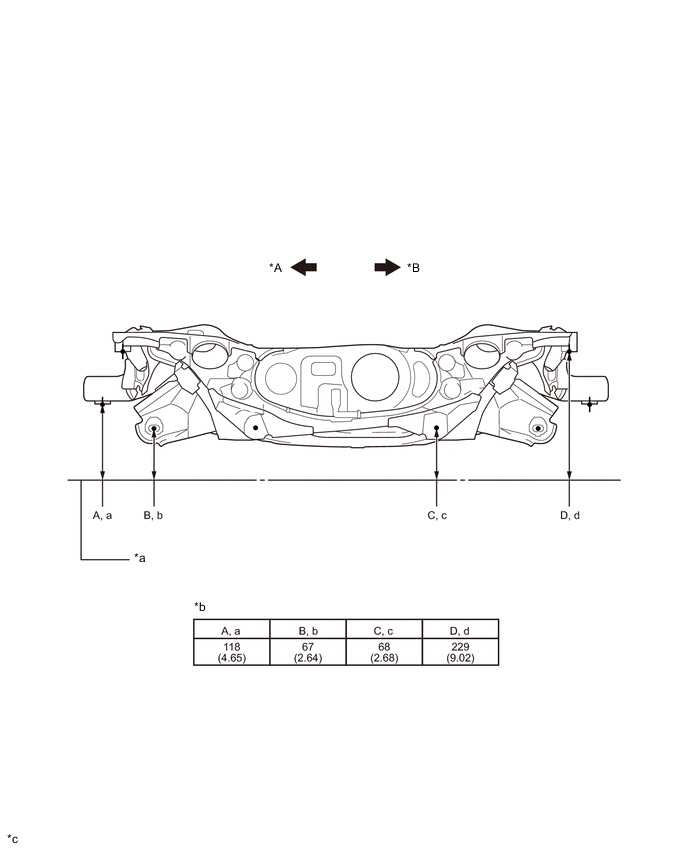
| *A | LH | *B | RH |
| *a | Imaginary Datum Line | *b | Height from Imaginary Datum Line |
| *c | mm (in.) |
- | - |