FIT STANDARD / ADJUSTMENT METHOD ADJUSTMENT
-
INSPECT HOOD SUB-ASSEMBLY
-
Check that the clearance measurements of areas "a" through "d" are within each standard range.
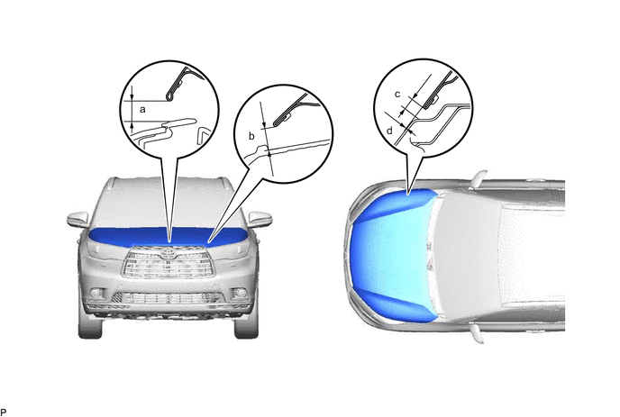
Standard Clearance Area Measurement Area Measurement a 9.31 to 12.31 mm (0.367 to 0.485 in.) b 8.91 to 11.91 mm (0.351 to 0.469 in.) c 3.4 to 6.4 mm (0.134 to 0.252 in.) d -1.4 to 1.6 mm (-0.0551 to 0.0630 in.) Tech Tips
Centering bolts are used to mount the hood hinge and hood lock. The hood and hood lock cannot be adjusted with the centering bolts installed. Substitute the centering bolts with standard bolts when making adjustments.
-
-
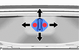
ADJUST HOOD SUB-ASSEMBLY
-
Horizontally and vertically adjust the hood.
-
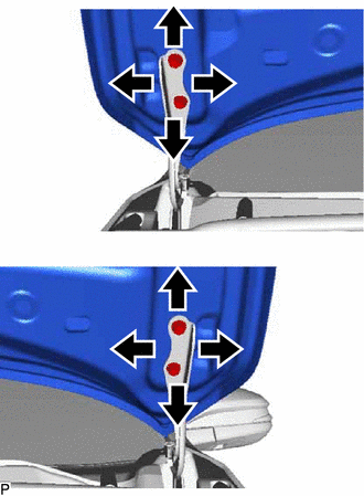
Loosen the hinge bolts of the hood.
-
Adjust the clearance between the hood and front fender by moving the hood.
-
Tighten the hinge bolts after adjustment.
- Torque:
- 13 N*m { 133 kgf*cm, 10 ft.*lbf }
-
-
Adjust the height of the front end of the hood using the hood bumper cushions.
-
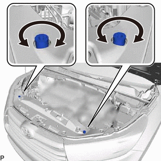
Adjust the hood bumper cushions so that the heights of the hood and fender are aligned.
Tech Tips
Raise or lower the front end of the hood by turning the hood bumper cushions.
-
-
Remove radiator grille.
-
Adjust the hood lock.
-
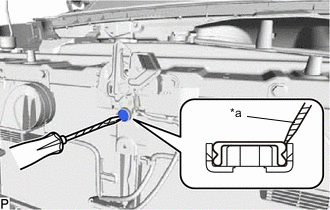
*a Protective Tape Using a screwdriver, remove the hood lock nut cap.
Tech Tips
Tape the screwdriver tip before use.
-
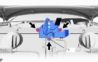
*1 Hood Lock Bolt Loosen the 2 bolts and hood lock bolt.
-
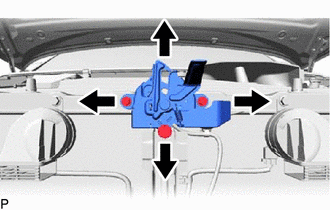
Adjust the hood lock and tighten the 2 bolts and hood lock bolt.
- Torque:
- 8.0 N*m { 82 kgf*cm, 71 in.*lbf }
-
Check that the striker can engage with the hood lock smoothly.
-
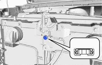
Install a new hood lock nut cap.
-
-
Install radiator grille.
-
-
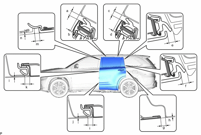
INSPECT FRONT DOOR
-
Check that the clearance measurements of areas "a" through "p" are within each standard range.
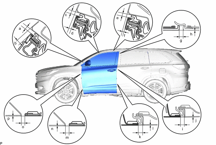
Standard Clearance Area Measurement Area Measurement a 3.35 to 6.35 mm (0.132 to 0.250 in.) b 6.15 to 9.15 mm (0.242 to 0.360 in.) c 3.35 to 6.35 mm (0.132 to 0.250 in.) d 2.35 to 5.35 mm (0.0925 to 0.211 in.) e 3.35 to 6.35 mm (0.132 to 0.250 in.) f 0.95 to 3.95 mm (0.0374 to 0.156 in.) g 2.3 to 6.3 mm (0.0906 to 0.248 in.) h -1.2 to 1.2 mm (-0.0472 to 0.0472 in.) i 3.2 to 5.6 mm (0.126 to 0.220 in.) j -1.2 to 1.2 mm (-0.0472 to 0.0472 in.) k 3.2 to 5.6 mm (0.126 to 0.220 in.) l -1.2 to 1.2 mm (-0.0472 to 0.0472 in.) m 2.8 to 5.2 mm (0.110 to 0.205 in.) n -1.2 to 1.2 mm (-0.0472 to 0.0472 in.) o 2.8 to 5.2 mm (0.110 to 0.205 in.) p -1.2 to 1.2 mm (-0.0472 to 0.0472 in.) Tech Tips
-
Use the same procedure for the RH side and LH side.
-
The following procedure is for the LH side.
-
Centering bolts are used to mount the door hinge to the vehicle body and door. The door cannot be adjusted with the centering bolts installed. Substitute the centering bolts with standard bolts when making adjustments.
-
-
-
REMOVE FRONT FENDER SIDE PANEL PROTECTOR
-
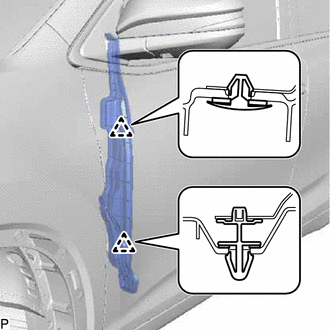
Remove the 2 clips and front fender side panel protector.
-
-
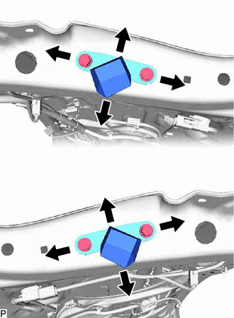
ADJUST FRONT DOOR
Note
Make sure to turn the ignition switch off when adjusting door lock strikers.
-
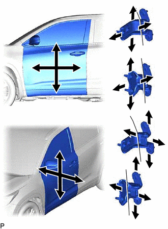
Using SST, loosen the 4 hinge bolts on the vehicle body and adjust the door position.
- SST
- 09812-00010
-
Tighten the 4 hinge bolts on the vehicle body after adjustment.
- Torque:
- 26 N*m { 265 kgf*cm, 19 ft.*lbf }
-
Loosen the 4 hinge bolts on the door and adjust the door position.
-
Tighten the 4 hinge bolts on the door after adjustment.
- Torque:
- 26 N*m { 265 kgf*cm, 19 ft.*lbf }
-
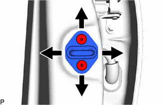
Using a T40 "TORX" socket wrench, slightly loosen 2 the striker mounting screws.
-
Using a brass bar and a hammer, hit the striker to adjust its position.
-
Using a T40 "TORX" socket wrench, tighten the 2 striker mounting screws after adjustment.
- Torque:
- 23 N*m { 235 kgf*cm, 17 ft.*lbf }
-
-
INSTALL FRONT FENDER SIDE PANEL PROTECTOR
-
Install the front fender side panel protector with 2 new clips.
-
-
INSPECT REAR DOOR
-
Check that the clearance measurements of areas "a" through "n" are within each standard range.
Standard Clearance Area Measurement Area Measurement a 3.35 to 6.35 mm (0.132 to 0.250 in.) b 0.65 to 6.35 mm (0.0256 to 0.250 in.) c 3.35 to 6.35 mm (0.132 to 0.250 in.) d 0.75 to 3.75 mm (0.0295 to 0.148 in.) e 4.5 to 8.5 mm (0.177 to 0.335 in.) f 4.5 to 8.5 mm (0.177 to 0.335 in.) g 3.5 to 5.5 mm (0.138 to 0.217 in.) h -1.5 to 1.5 mm (-0.0591 to 0.0591 in.) i 3.2 to 5.6 mm (0.126 to 0.220 in.) j -1.2 to 1.2 mm (-0.0472 to 0.0472 in.) k 3.2 to 5.6 mm (0.126 to 0.220 in.) l -1.2 to 1.2 mm (-0.0472 to 0.0472 in.) m 4.3 to 6.3 mm (0.169 to 0.248 in.) n -1.2 to 1.2 mm (-0.0472 to 0.0472 in.) Tech Tips
-
Use the same procedure for the RH side and LH side.
-
The following procedure is for the LH side.
-
Centering bolts are used to mount the door hinge to the vehicle body and door. The door cannot be adjusted with the centering bolts installed. Substitute the centering bolts with standard bolts when making adjustments.
-
-
-
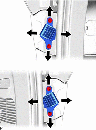
ADJUST REAR DOOR
Note
Make sure to turn the ignition switch off when adjusting door lock strikers.
-
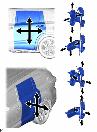
Using SST, loosen the 4 hinge bolts on the vehicle body and adjust the door position.
- SST
- 09812-00010
-
Tighten the 4 hinge bolts on the vehicle body after adjustment.
- Torque:
- 26 N*m { 265 kgf*cm, 19 ft.*lbf }
-
Loosen the 4 hinge bolts on the door and adjust the door position.
-
Loosen the 4 hinge bolts on the door and adjust the door position.
- Torque:
- 26 N*m { 265 kgf*cm, 19 ft.*lbf }
-
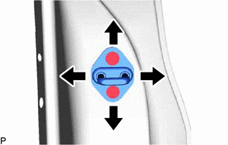
Using a T40 "TORX" socket wrench, slightly loosen the 2 striker mounting screws.
-
Using a brass bar and a hammer, hit the striker to adjust its position.
-
Using a T40 "TORX" socket wrench, tighten the 2 striker mounting screws after adjustment.
- Torque:
- 23 N*m { 235 kgf*cm, 17 ft.*lbf }
-
-
INSPECT BACK DOOR
-
Check that the clearance measurements of areas "a" through "m" are within each standard range.
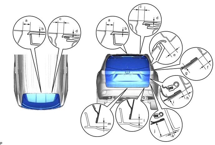
Standard Clearance Area Measurement Area Measurement a 9.0 to 13.0 mm (0.354 to 0.512 in.) b 0 to 3.5 mm (0.00 to 0.138 in.) c 7.4 to 11.4 mm (0.291 to 0.449 in.) d 0 to 3.5 mm (0.00 to 0.138 in.) e 6.0 to 10.0 mm (0.236 to 0.394 in.) f 5.4 to 8.4 mm (0.213 to 0.331 in.) g 0.2 to 3.2 mm (0.00787 to 0.126 in.) h 4.8 to 7.8 mm (0.189 to 0.307 in.) i -0.4 to 2.6 mm (-0.0157 to 0.102 in.) j 21.5 to 25.5 mm (0.847 to 1.00 in.) k 4.3 to 8.3 mm (0.169 to 0.327 in.) l 4.8 to 8.8 mm (0.189 to 0.346 in.) m 4.8 to 8.8 mm (0.189 to 0.346 in.) - - Tech Tips
Centering bolts are used to mount the door hinge to the vehicle body and door. The door cannot be adjusted with the centering bolts installed. Substitute the centering bolts with standard bolts (with washers) when making adjustments.
-
-
ADJUST BACK DOOR
-
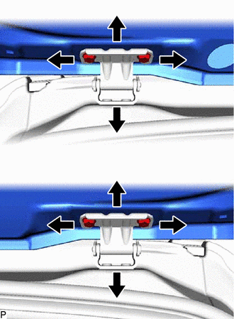
Before adjusting the upper end of the back door up and down or left and right, loosen the 4 bolts.
-
Tighten the body side hinge after adjustment.
- Torque:
- 19.5 N*m { 199 kgf*cm, 14 ft.*lbf }
-
Using a T40 "TORX" socket wrench, slightly loosen the striker mounting 2 screws.
-
Using a brass bar and a hammer, hit the striker to adjust its position.
-
Using a T40 "TORX" socket wrench, tighten the striker mounting 2 screws after adjustment.
- Torque:
- 23 N*m { 235 kgf*cm, 17 ft.*lbf }
-
After adjusting the back door position, adjust the position of the back door lower stoppers.
- Torque:
- 7.5 N*m { 76 kgf*cm, 66 in.*lbf }
-
After adjusting the back door position, adjust the position of the back door stopper brackets.
- Torque:
- 7.5 N*m { 76 kgf*cm, 66 in.*lbf }
-