FRONT SIDE MEMBER CUT AND JOIN REPLACEMENT SECTIONS (SMALL AREAS)
-
With the radiator side support and radiator lower support removed.
-
REMOVAL
Symbol meaning 
Remove Weld Points 
Remove Weld Points 
Cut and Join Location
-
Carefully cut the front side member sub-assembly inner so not to damage *a.
REMOVAL POINT
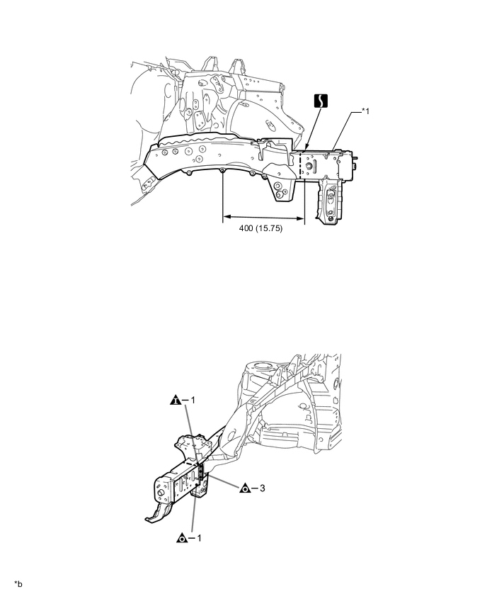
*1 FRONT SIDE MEMBER SUB-ASSEMBLY INNER - - *b mm (in.) - - 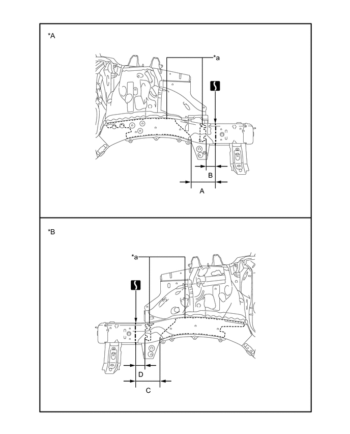
*A LH *B RH Reference Value Area Measurement Area Measurement A 165 mm (6.50 in.) B 65 mm (2.56 in.) C 165 mm (6.50 in.) D 65 mm (2.56 in.) -
-
INSTALLATION
Symbol meaning 
Plug Weld 
Plug Weld 
Butt Weld
-
Temporarily install the new parts and measure each part of the new parts in accordance with the body dimension diagram. (See the body dimensions)
-
Make sure to attach correctly in accordance with the body dimension diagram as this part affects the front wheel alignment.
-
After welding, apply body sealer and undercoating to the corresponding parts. (See the painting / coating)
-
After applying the top coat, apply anti-rust agent to the internal panel portion of the closed section structural weld points.
INSTALLATION POINT
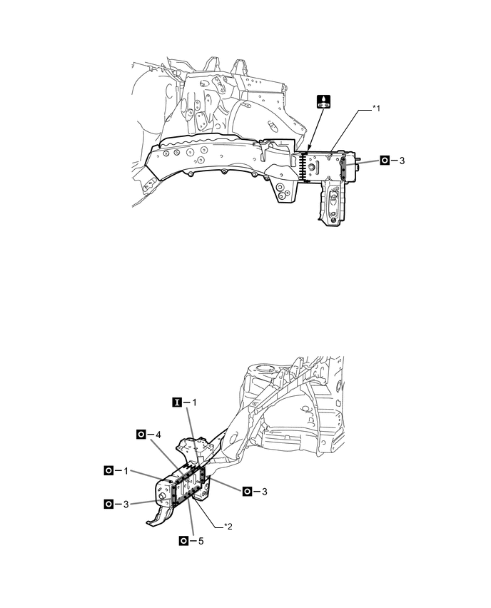
*1 FRONT SIDE MEMBER SUB-ASSEMBLY INNER *2 FRONT SIDE MEMBER EXTENSION -