WHEN REMOVING,INSTALLING,REPAIRING OR REPLACING PARTS WHEEL ALIGNMENT STANDARD
Note
If a wheel alignment has been performed, or if suspension or underbody components have been removed/installed or replaced, be sure to perform the following initialization procedure in order for the system to function normally:
-
Perform zero point calibration of the yaw rate and acceleration sensor.
-
MEASURE VEHICLE HEIGHT
Note
-
Before inspecting the wheel alignment, adjust the vehicle height to the specified value.
-
Be sure to perform measurement on a level surface.
-
If it is necessary to go under the vehicle for measurement, confirm that the parking brake is applied and the vehicle is secured with chocks.
-
Inspect while the vehicle is unloaded.
-
The standard value shown here is a value that is used for performing a wheel alignment and does not indicate the height of an actual vehicle.
-
Bounce the vehicle up and down at the corners to stabilize the suspension.
-
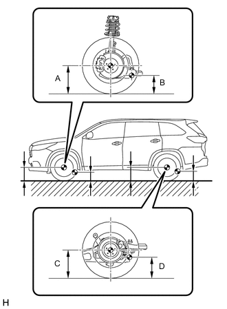
Measure the vehicle height.
-
A: Ground clearance of front wheel center
Measurement Points:
-
B: Ground clearance of front lower suspension arm bushing set bolt center
-
C: Ground clearance of rear wheel center
-
D: Ground clearance of rear No. 2 suspension arm set bolt center
-
-
-
FRONT WHEEL ALIGNMENT
-
INSPECT CAMBER, CASTER AND STEERING AXIS INCLINATION
Note
Inspect while the vehicle is unloaded.
-
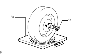
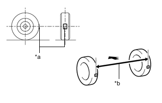
*a Turning Radius Gauge *b Camber-caster-kingpin Gauge Install a camber-caster-kingpin gauge and place the front wheels on the center of a turning radius gauge.
-
Inspect the camber, caster and steering axis inclination.
-
-
INSPECT TOE-IN
Note
Inspect while the vehicle is unloaded.
-
Bounce the vehicle up and down at the corners to stabilize the suspension.
-
Release the parking brake and move the shift lever to N.
-
Push the vehicle straight ahead approximately 5 m (16.4 ft.). (Step C)
-

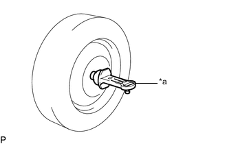
*a Tread Center Mark *b Dimension B 
Front of the Vehicle Put tread center marks on the rearmost points of the front wheels and measure the distance between the marks (dimension B).
-
Slowly push the vehicle straight ahead to cause the front wheels to rotate 180°. Use the front tire valve as a reference point.
Tech Tips
Do not allow the wheels to rotate more than 180°. If the wheels rotate more than 180°, perform the procedure from step C again.
-
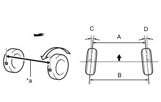
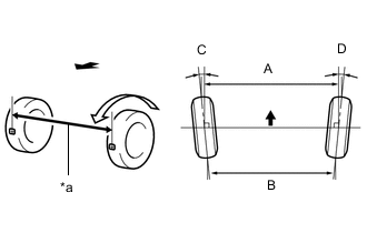
*a Dimension A Front of the Vehicle Measure the distance between the tread center marks on the front of the wheels (dimension A).
Tech Tips
Measure "B - A" only when "C + D" cannot be measured.
If the toe-in is not within the specified range, adjust it at the steering rack ends.
-
-
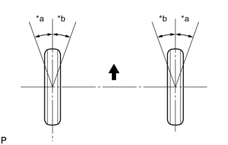
*a Inside *b Outside Front of the Vehicle INSPECT WHEEL ANGLE
-
Put tread center marks on the rearmost points of a turning radius gauge.
-
Turn the steering wheel fully to the left and right and measure the turning angle.
Note
Inspect while the vehicle is unloaded.
-
If the right and left inside wheel angles differ from the specified value, check and adjust the right and left steering rack end lengths.
-
-
-
-
REAR WHEEL ALIGNMENT
-
*a Camber-caster-kingpin Gauge INSPECT CAMBER
Note
Inspect while the vehicle is unloaded.
-
Install a camber-caster-kingpin gauge.
-
Inspect the camber.
Tech Tips
Camber is not adjustable. If the measurement is not within the specified range, inspect the suspension parts for damage and/or wear, and replace them if necessary.
-
-
INSPECT TOE-IN
Note
Inspect while the vehicle is unloaded.
-
Bounce the vehicle up and down at the corners to stabilize the suspension.
-
Release the parking brake and move the shift lever to N.
-
Push the vehicle straight ahead approximately 5 m (16.4 ft.). (Step A)
-
*a Tread Center Mark *b Dimension B Front of the Vehicle Put tread center marks on the rearmost points of the rear wheels and measure the distance between the marks (dimension B).
-
Slowly push the vehicle straight ahead to cause the rear wheels to rotate 180°. Use the rear tire valve as a reference point.
Tech Tips
Do not allow the wheels to rotate more than 180°. If the wheels rotate more than 180°, perform the procedure from step A again.
-
*a Dimension A Front of the Vehicle Measure the distance between the tread center marks on the front of the rear wheels (dimension A).
Tech Tips
Measure "B - A" only when "C + D" cannot be measured.
If the toe-in is not within the specified range, adjust it by following the procedures below.
-
-