FIT STANDARD / ADJUSTMENT METHOD ADJUSTMENT
-
INSPECT HOOD SUB-ASSEMBLY
-
Check that the clearance measurements of areas a through f are within each standard range.
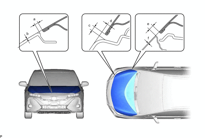
Standard Clearance Area Measurement Area Measurement a 1.45 to 5.45 mm (0.0571 to 0.215 in.) b -1.85 to 2.15 mm (-0.0728 to 0.0846 in.) c 3.05 to 7.05 mm (0.12 to 0.278 in.) d 1.85 to 5.85 mm (0.0728 to 0.23 in.) e 3.4 to 6.4 mm (0.134 to 0.252 in.) f -1.5 to 1.5 mm (-0.0591 to 0.0591 in.)
Tech Tips
Centering bolts are used to install the hood hinges and hood lock. The hood and hood lock cannot be adjusted with the centering bolts installed. Substitute the centering bolts with standard bolts with washers when making adjustments.
-
-
ADJUST HOOD SUB-ASSEMBLY
-
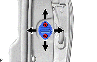
Horizontally and vertically adjust the hood.
-
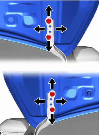
Loosen the 4 hinge bolts of the hood.
-
Adjust the clearance between the hood and front fenders by moving the hood.
-
Tighten the 4 hinge bolts after adjustment.
- Torque:
- 13 N*m { 133 kgf*cm, 10 ft.*lbf }
-
-
Adjust the height of the front end of the hood using the hood bumper cushions.
-
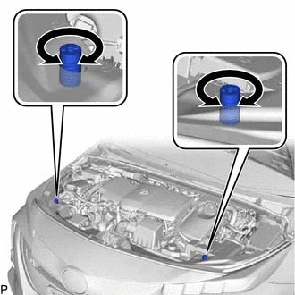
Adjust the 2 hood bumper cushions so that the heights of the hood and fenders are aligned.
Tech Tips
Raise or lower the front end of the hood by turning the 2 hood bumper cushions.
-
-
Adjust the hood lock.
-
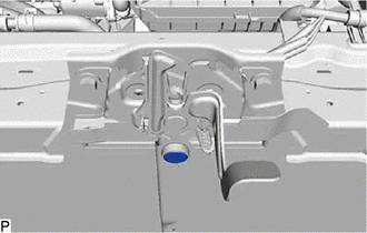
Remove the radiator support opening cover.
-
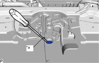
*a Protective Tape Using a screwdriver with its tip wrapped with protective tape, remove the hood lock nut cap.
-
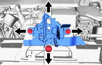
*1 Hood Lock Bolt Loosen the 2 bolts and hood lock bolt.
-
Adjust the hood lock assembly and tighten the 2 bolts and hood lock bolt.
- Torque:
- 8.0 N*m { 82 kgf*cm, 71 in.*lbf }
-
Check that the striker can engage the hood lock assembly smoothly.
-
Install a new hood lock nut cap.
-
Install the radiator support opening cover.
-
-
-
INSPECT FRONT DOOR
-
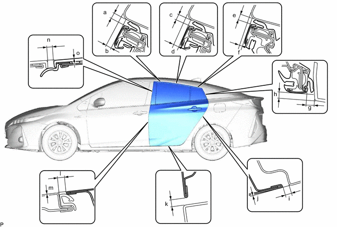
Check that the clearance measurements of areas a through n are within each standard range.
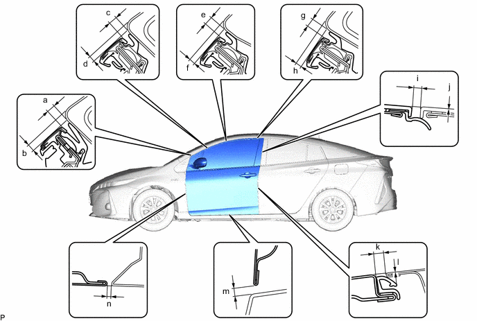
Standard Clearance Area Measurement Area Measurement a 3.15 to 6.55 mm (0.124 to 0.258 in.) b 2.85 to 6.85 mm (0.112 to 0.270 in.) c 3.15 to 6.55 mm (0.124 to 0.258 in.) d 1.65 to 5.65 mm (0.0650 to 0.222 in.) e 3.15 to 6.55 mm (0.124 to 0.258 in.) f 1.75 to 5.75 mm (0.0689 to 0.226 in.) g 3.15 to 6.55 mm (0.124 to 0.258 in.) h 1.55 to 5.55 mm (0.0610 to 0.219 in.) i 2.5 to 6.5 mm (0.0984 to 0.256 in.) j -2.0 to 2.0 mm (-0.0787 to 0.0787 in.) k 3.0 to 5.4 mm (0.118 to 0.213 in.) l -1.2 to 1.2 mm (-0.0472 to 0.0472 in.) m 3.55 to 7.75 mm (0.140 to 0.305 in.) n 2.6 to 5.6 mm (0.102 to 0.220 in.)
Tech Tips
-
Use the same procedure for the RH side and LH side.
-
The following procedure is for the LH side.
-
Centering bolts are used to install the door hinges to the vehicle body and door. The door cannot be adjusted with the centering bolts installed. Substitute the centering bolts with standard bolts when making adjustments.
-
-
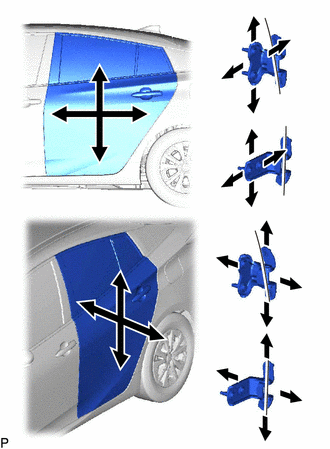
ADJUST FRONT DOOR
Note
Make sure to turn the power switch off before adjusting the door lock strikers.
-
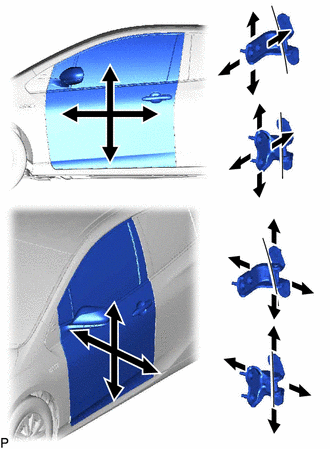
Using SST, loosen the 4 hinge bolts on the vehicle body and adjust the door position.
- SST
- 09812-00020
-
Tighten the 4 hinge bolts on the vehicle body after adjustment.
- Torque:
- 26 N*m { 265 kgf*cm, 19 ft.*lbf }
-
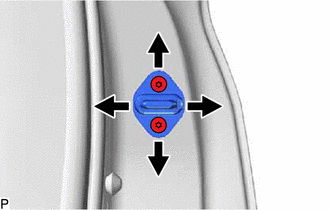
Loosen the 4 hinge bolts on the door and adjust the door position.
-
Tighten the 4 hinge bolts on the door after adjustment.
- Torque:
- 21 N*m { 214 kgf*cm, 15 ft.*lbf }
-
Using a T40 "TORX" socket wrench, slightly loosen the 2 striker mounting screws.
-
Using a brass bar and a hammer, hit the striker to adjust its position.
-
Using a T40 "TORX" socket wrench, tighten the 2 striker mounting screws after adjustment.
- Torque:
- 23 N*m { 235 kgf*cm, 17 ft.*lbf }
-
-
INSPECT REAR DOOR
-
Check that the clearance measurements of areas a through o are within each standard range.
Standard Clearance Area Measurement Area Measurement a 3.15 to 6.55 mm (0.124 to 0.258 in.) b 2.75 to 6.75 mm (0.108 to 0.266 in.) c 3.15 to 6.55 mm (0.124 to 0.258 in.) d 1.95 to 5.95 mm (0.0768 to 0.234 in.) e 3.15 to 6.55 mm (0.124 to 0.258 in.) f 0.95 to 4.95 mm (0.0374 to 0.195 in.) g 4.5 to 7.9 mm (0.177 to 0.311 in.) h 4.0 to 8.0 mm (0.157 to 0.315 in.) i 2.5 to 6.5 mm (0.0984 to 0.256 in.) j -1.5 to 1.5 mm (-0.0591 to 0.0591 in.) k 3.55 to 7.75 mm (0.140 to 0.305 in.) l 3.0 to 5.4 mm (0.118 to 0.213 in.) m -1.2 to 1.2 mm (-0.0472 to 0.0472 in.) n 2.5 to 6.5 mm (0.0984 to 0.256 in.) o -2.0 to 2.0 mm (-0.0787 to 0.0787 in.) - -
Tech Tips
-
Use the same procedure for the RH side and LH side.
-
The following procedure is for the LH side.
-
Centering bolts are used to install the door hinges to the vehicle body and door. The door cannot be adjusted with the centering bolts installed. Substitute the centering bolts with standard bolts when making adjustments.
-
-
ADJUST REAR DOOR
Note
Make sure to turn the power switch off before adjusting the door lock strikers.
-
Using SST, loosen the 4 hinge bolts on the vehicle body and adjust the door position.
- SST
- 09812-00020
-
Tighten the 4 hinge bolts on the vehicle body after adjustment.
- Torque:
- 26 N*m { 265 kgf*cm, 19 ft.*lbf }
-
Loosen the 4 hinge bolts on the door and adjust the door position.
-
Tighten the 4 hinge bolts on the door after adjustment.
- Torque:
- 21 N*m { 214 kgf*cm, 15 ft.*lbf }
-
Using a T40 "TORX" socket wrench, slightly loosen the 2 striker mounting screws.
-
Using a brass bar and a hammer, hit the striker to adjust its position.
-
Using a T40 "TORX" socket wrench, tighten the 2 striker mounting screws after adjustment.
- Torque:
- 23 N*m { 235 kgf*cm, 17 ft.*lbf }
-
-
INSPECT BACK DOOR
-
Check that the clearance measurements of areas a through l are within each standard range.
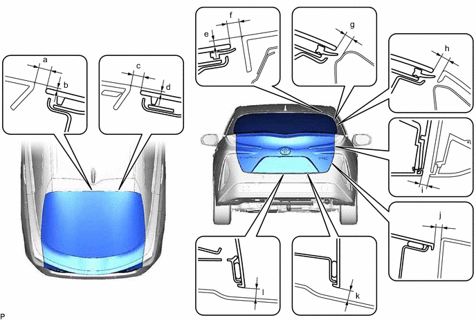
Standard Clearance Area Measurement Area Measurement a 5.6 to 10.6 mm (0.22 to 0.417 in.) b -0.5 to 4.5 mm (-0.0197 to 0.177 in.) c 5.6 to 10.6 mm (0.22 to 0.417 in.) d -0.5 to 4.5 mm (-0.0197 to 0.177 in.) e 1.7 to 6.7 mm (0.0669 to 0.264 in.) f 5.6 to 10.6 mm (0.22 to 0.417 in.) g 3.35 to 8.35 mm (0.132 to 0.329 in.) h 3.5 to 8.5 mm (0.138 to 0.335 in.) i 3.7 to 8.7 mm (0.146 to 0.343 in.) j 3.7 to 8.7 mm (0.146 to 0.343 in.) k 7.5 to 11.5 mm (0.295 to 0.453 in.) l 7.5 to 11.5 mm (0.295 to 0.453 in.)
Tech Tips
Centering bolts are used to install the door hinges to the door. The door cannot be adjusted with the centering bolts installed. Substitute the centering bolts with standard bolts (with washers) when making adjustments.
-
-
ADJUST BACK DOOR
-
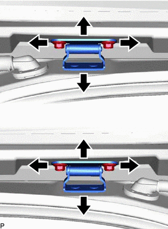
Loosen the 4 hinge bolts on the back door and adjust the back door position.
-
Tighten the 4 hinge bolts on the back door after adjustment.
- Torque:
- 31 N*m { 316 kgf*cm, 23 ft.*lbf }
-
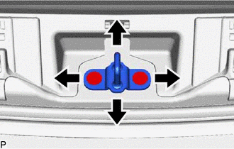
Using a T40 "TORX" socket wrench, slightly loosen the 2 striker mounting screws.
-
Using a brass bar and a hammer, hit the striker to adjust its position.
-
Using a T40 "TORX" socket wrench, tighten the 2 striker mounting screws after adjustment.
- Torque:
- 23 N*m { 235 kgf*cm, 17 ft.*lbf }
-