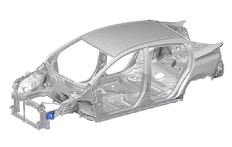
FRONT SIDE MEMBER EXTENSION ASSEMBLY REPLACEMENT
-
With the fender apron brace assembly removed.
-
REMOVAL
Symbol Meaning 
Remove Weld Points 
Remove Weld Points
-
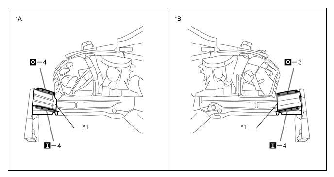
Remove the front side member extension sub-assembly.
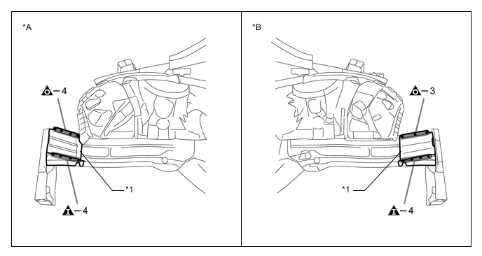
*A LH *B RH *1 FRONT SIDE MEMBER EXTENSION SUB-ASSEMBLY - - -
Remove the front side member sub-assembly outer.
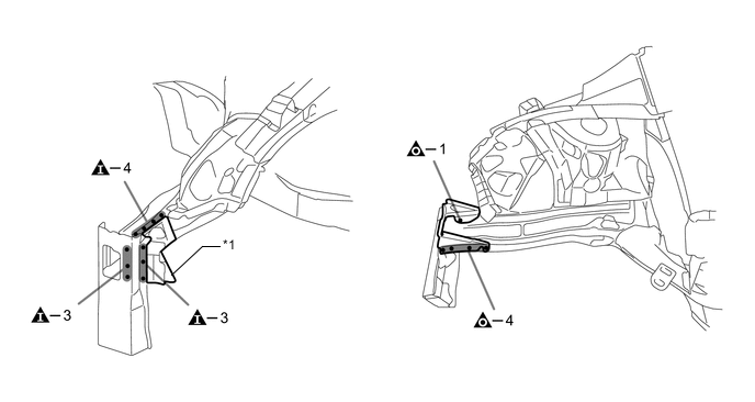
*1 FRONT SIDE MEMBER SUB-ASSEMBLY OUTER - -
-
-
INSTALLATION
Symbol Meaning 
Plug Weld 
Plug Weld
-
Temporarily install the new parts and measure each part of the new parts in accordance with the body dimension diagram. (See the body dimensions)
-
Weld the front side member sub-assembly outer to the vehicle side.
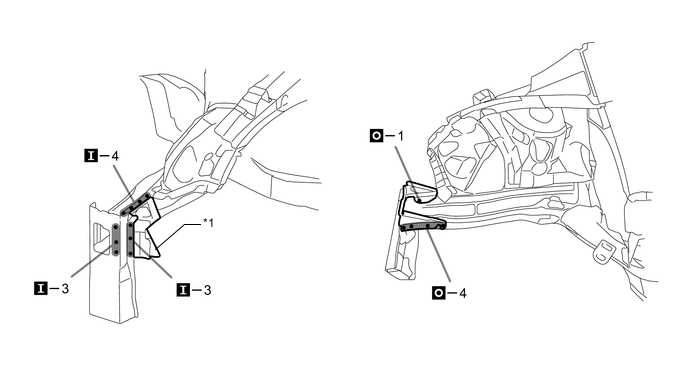
*1 FRONT SIDE MEMBER SUB-ASSEMBLY OUTER - - -
Weld the front side member extension sub-assembly to the vehicle side.
*A LH *B RH *1 FRONT SIDE MEMBER EXTENSION SUB-ASSEMBLY - - -
After applying the top coat, apply anti-rust agent to the internal panel portion of the closed section structural weld points.
-