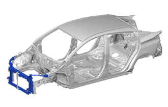
RADIATOR SUPPORT ASSEMBLY REPLACEMENT
-
REMOVAL
Symbol Meaning 
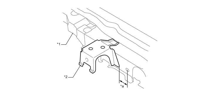
Remove Weld Points 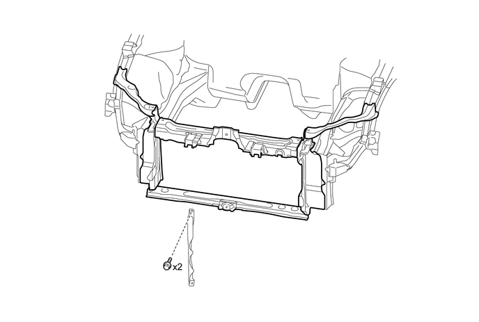
-
Perform the replacement with the A attached to the vehicle.
Tech Tips
If the A is damaged, replace the A.
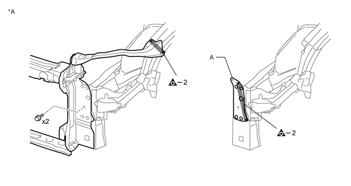
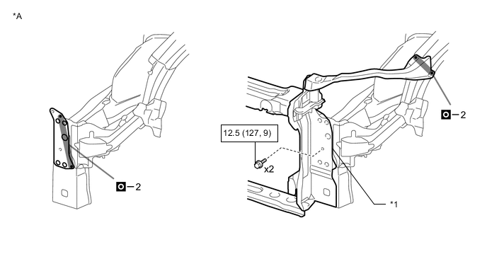
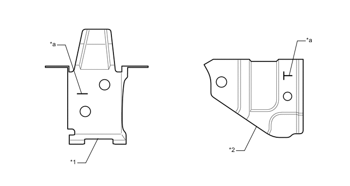
*A LH Side - - 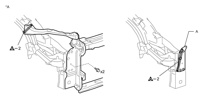
*A RH Side - -
-
-
INSTALLATION
Symbol Meaning 
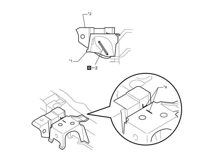
Plug Weld
-
Inspect the fitting of the related parts around the new parts before welding. This affects the appearance of the finish.
-
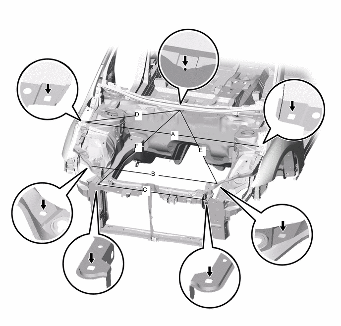
Temporarily install the new parts and measure each part of the new parts in accordance with the body dimension diagram. (See the body dimensions)
*A LH Side - - *1 RADIATOR SUPPORT SUB-ASSEMBLY - - 
N*m (kgf*cm, ft.*lbf) : Specified torque - - 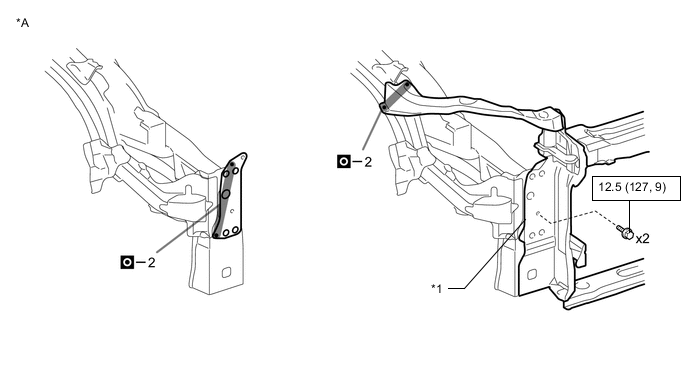
*A RH Side - - *1 RADIATOR SUPPORT SUB-ASSEMBLY - - N*m (kgf*cm, ft.*lbf) : Specified torque - - 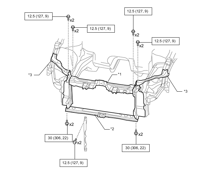
*1 RADIATOR SUPPORT SUB-ASSEMBLY UPPER *2 RADIATOR SUPPORT SUB-ASSEMBLY LOWER *3 RADIATOR SUPPORT UPPER - - N*m (kgf*cm, ft.*lbf) : Specified torque - - -
After applying the top coat, apply anti-rust agent to the internal panel portion of the closed section structural weld points.
-
Measure the dimensions before installing the headlights.
-
Position of marks for body repair
*1 FRONT BUMPER STAY SUB-ASSEMBLY *2 RADIATOR GRILLE MOUNTING BRACKET *a MARK FOR BODY REPAIR - - -
Weld the front bumper stay sub-assembly to the radiator upper support.
Tech Tips
The values shown here are reference values. Use for temporary installation.
*1 RADIATOR UPPER SUPPORT *2 FRONT BUMPER STAY SUB-ASSEMBLY *a 29 mm (1.14 in.) - - 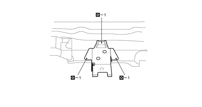
-
Weld the radiator grille mounting bracket to the front bumper stay sub-assembly.
Tech Tips
Determine the vertical and horizontal orientation of the radiator grille mounting bracket by using the marks for body repair.
*1 FRONT BUMPER STAY SUB-ASSEMBLY *2 RADIATOR GRILLE MOUNTING BRACKET *a MARK FOR BODY REPAIR - -
-