UNDER BODY (for AWD) TWO-DIMENSIONAL DISTANCE
Tech Tips
-
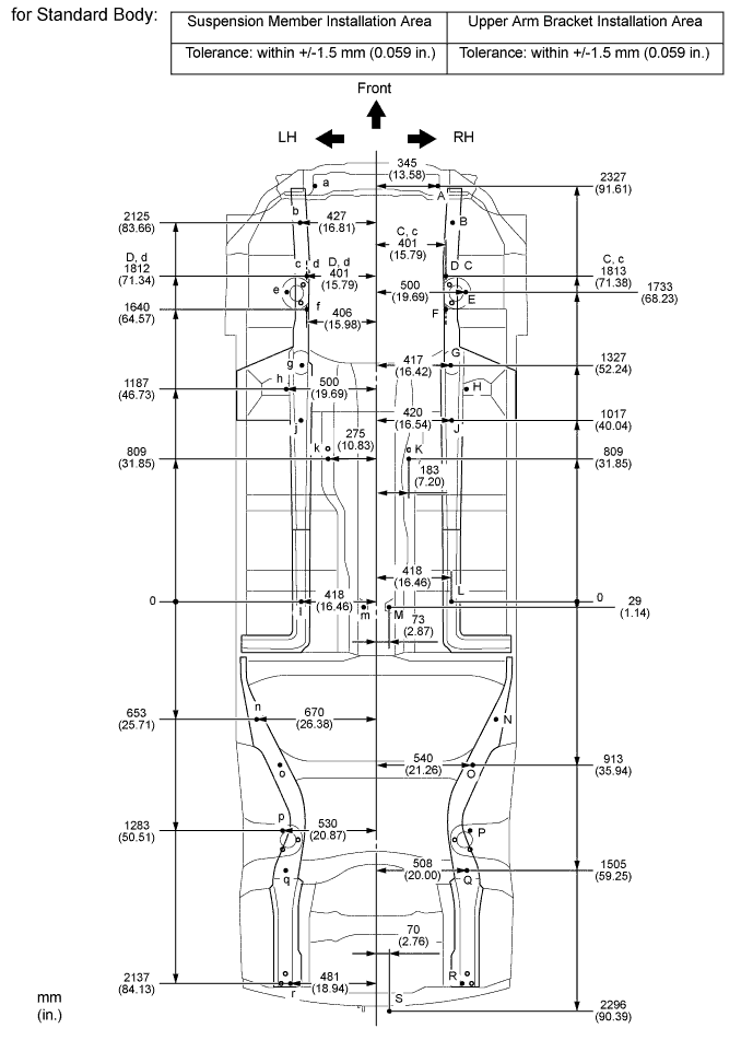
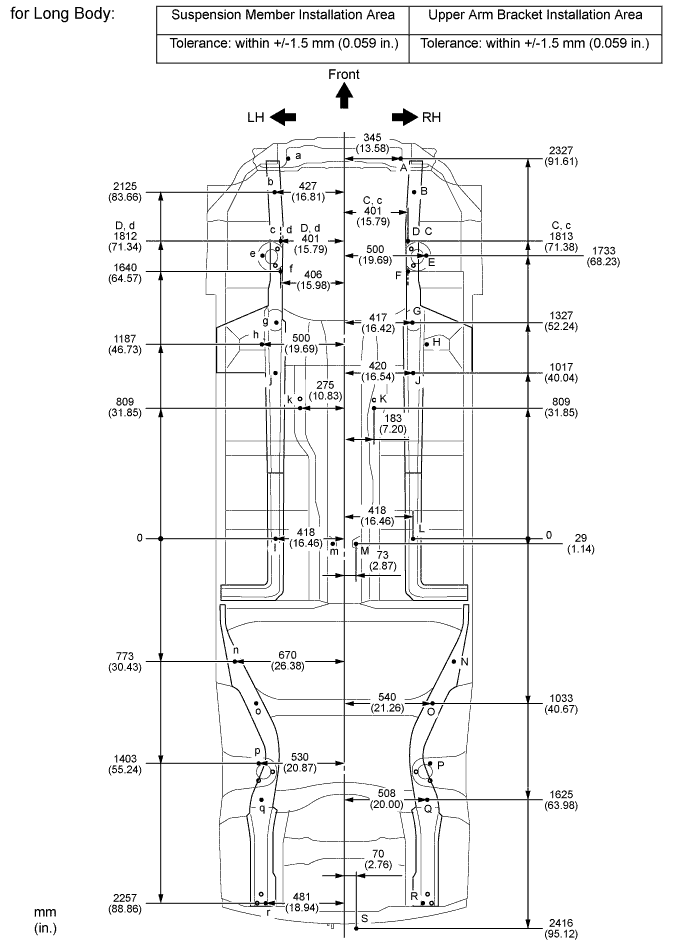
Length measurements are indicated at the points where the arrows extending from the zero point intersect the lines that extend towards the outside of the illustration from each point.
-
Point K, k on the vehicle are asymmetrical.
-
In cases in which only one dimension is given, left and right are symmetrical.
-
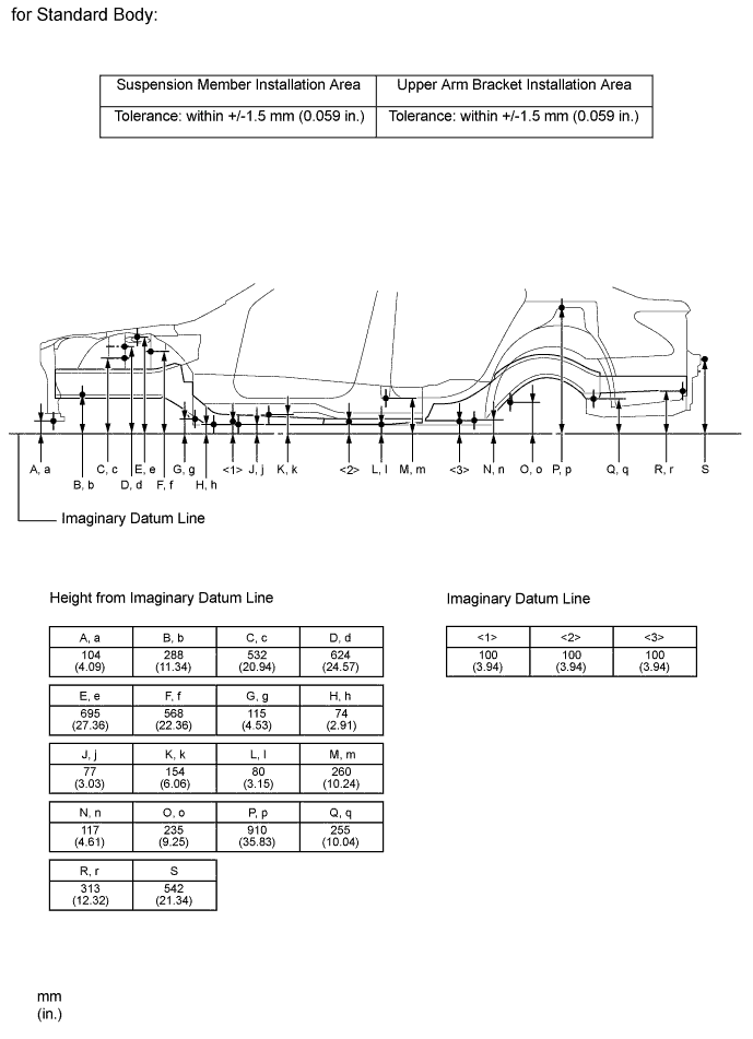
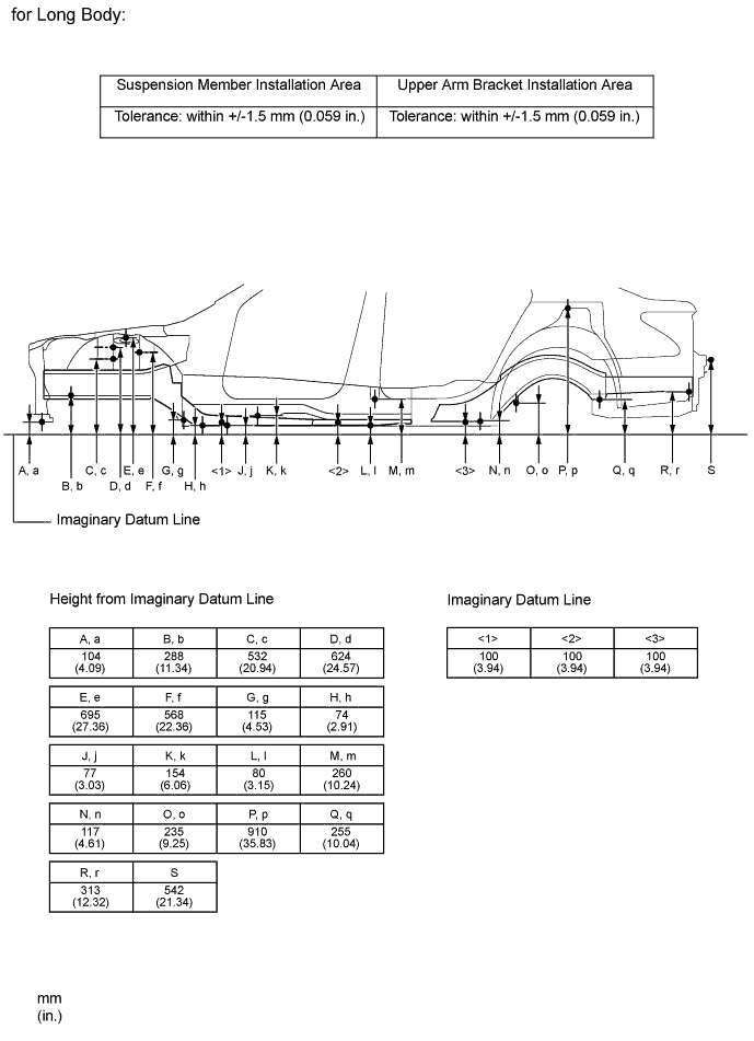
For symbols, capital letters indicate right side of vehicle, small letters indicate left side of vehicle (seen from rear).
| Symbol | Name | Hole Diameter mm (in.) |
|---|---|---|
| A, a | Front Crossmember Standard Hole | φ13 (0.51) |
| B, b | Front Suspension Crossmember Installation Nut | M16 (0.63) |
| C, c | Arm Attachment Inner No. 1 Plate Installation Hole | φ13 (0.51) |
| D, d | Arm Attachment Inner No. 1 Plate Installation Hole | φ10.4 (0.41) |
| E, e | Front Spring Support Hole | φ13 (0.51) |
| F, f | Arm Attachment Inner No. 2 Plate Installation Hole | φ10.4 (0.41) |
| G, g | Front Suspension Crossmember Installation Nut | M16 (0.63) |
| H, h | Torque Front Box Standard Hole | φ25 (0.98) |
| J, j | Front Side Member No. 5 Reinforcement Standard Hole | φ18 (0.71) |
| K, k | Engine Rear Mounting Member Installation Nut | M10 (0.39) |
| L, l | Front Floor Under Reinforcement Standard Hole | φ15 (0.59) |
| M, m | Propeller w/ Center Bearing Shaft Installation Nut | M10 (0.39) |
| N, n | Rear Floor Side Member Standard Hole | φ18 (0.71) |
| O, o | Rear Suspension Member Installation Nut | M14 (0.55) |
| P, p | Rear Spring Support Hole | φ13 (0.51) |
| Q, q | Rear Suspension Member Installation Nut | M14 (0.55) |
| R, r | Exhaust Pipe No. 3 Support Installation Nut | M8 (0.31) |
| S | Millimeter Wave Radar Rear Sensor Installation Bolt | M6 (0.24) |
| for Standard Body | 2970 mm (116.93 in.) |
| for Long Body | 3090 mm (121.65 in.) |