FRONT SIDE MEMBER CUT AND JOIN REPLACEMENT SECTIONS (LARGE AREAS)
-
With the front fender front apron removed.
-
REMOVAL
Symbol Meaning 
Remove Weld Points 
Remove Weld Points 
Cut with Disc Sander etc. 
Cut and Join Location
-
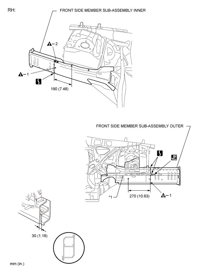
Carefully cut the front side member sub-assembly outer so not to damage *1.
-
Carefully cut the front side member sub-assembly inner so not to damage *2.
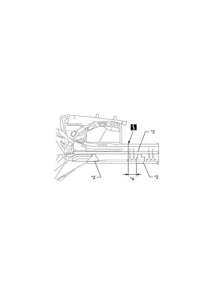
REMOVAL POINTReference Value Area Measurement Area Measurement *a 80 mm (3.15 in.) - - 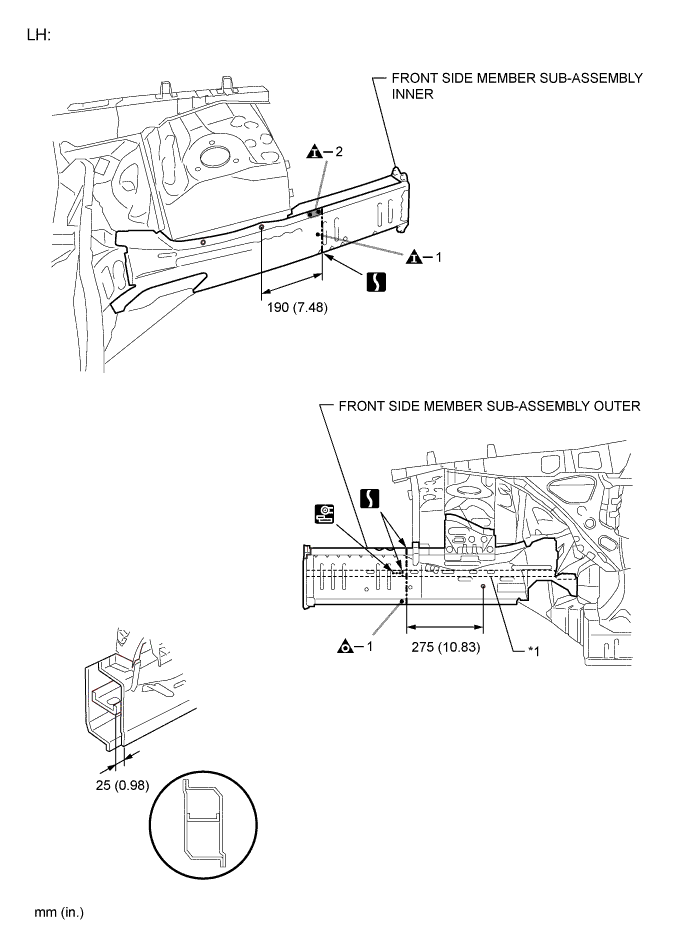
-
-
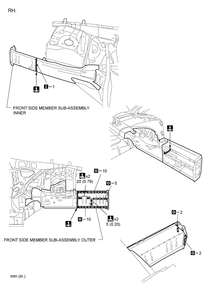
INSTALLATION
Symbol Meaning 
Plug Weld 
Plug Weld 
Fillet Weld 
Butt Weld
-
Temporarily install the new parts and measure each part of the new parts in accordance with the body dimension diagram. (See the body dimensions)
-
After welding the front side member sub-assembly inner to the vehicle side, install the front side member sub-assembly outer.
-
After applying the top coat, apply anti-rust agent to the internal panel portion of the closed section structural weld points.
INSTALLATION POINT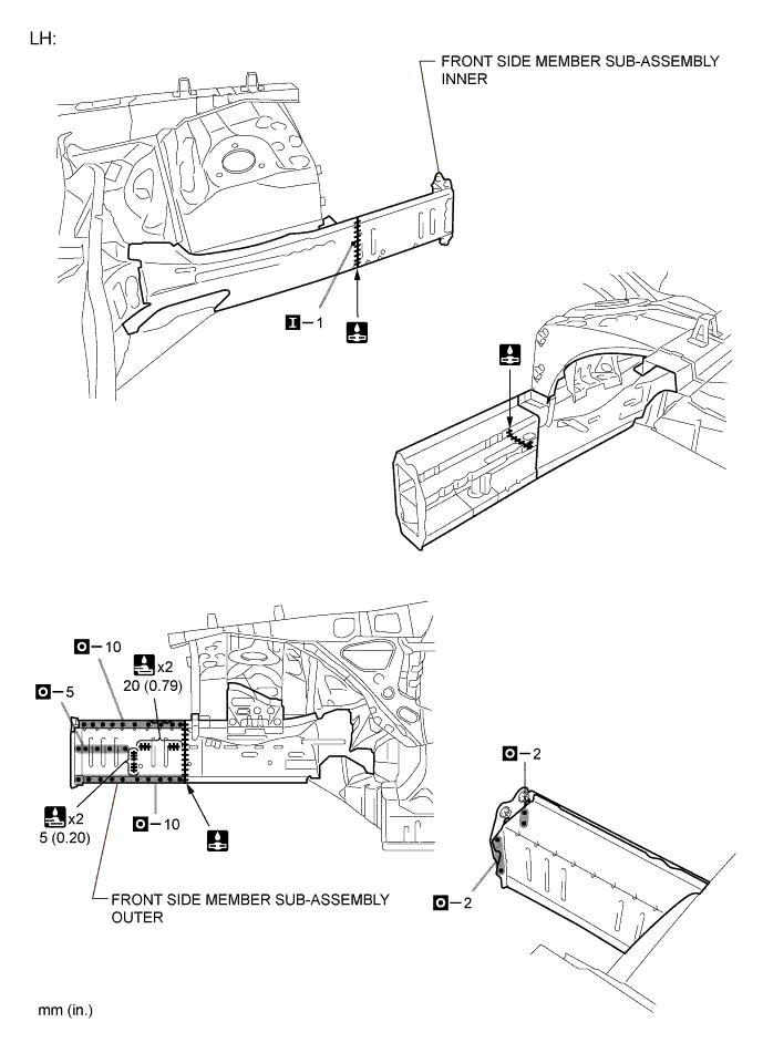
-