FIT STANDARD / ADJUSTMENT METHOD ADJUSTMENT
-
INSPECT HOOD SUB-ASSEMBLY
-
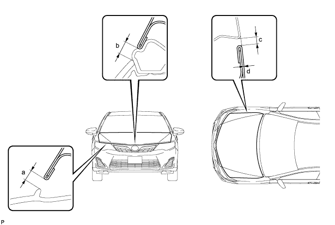
Check that the clearance measurements of areas a through d are within each standard range.
Reference Value Area Measurement Area Measurement *a 2.45 to 6.45 mm (0.0965 to 0.254 in.) *b 3.55 to 7.55 mm (0.140 to 0.297 in.) *c 2.0 to 5.0 mm (0.0787 to 0.197 in.) *d -1.5 to 1.5 mm (-0.0591 to 0.0591 in.) Tech Tips
Centering bolts are used to mount the hood hinge and hood lock. The hood and hood lock cannot be adjusted with the centering bolts installed. Substitute the centering bolts with standard bolts when making adjustments.
-
-
ADJUST HOOD SUB-ASSEMBLY
-
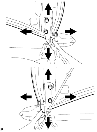
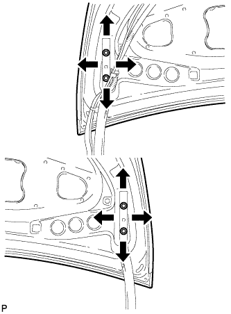
Horizontally and vertically adjust the hood.
-
Loosen the 4 hinge bolts of the hood.
-
Adjust the clearance between the hood and front fender by moving the hood.
-
Tighten the 4 hinge bolts after the adjustment.
- Torque:
- 13 N*m { 133 kgf*cm, 10 ft.*lbf }
-
-
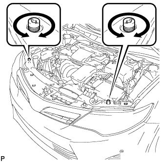
Adjust the height of the front end of the hood using the cushion rubbers.
-
Adjust the 2 cushion rubbers so that the heights of the hood and fender are aligned.
Tech Tips
Raise or lower the front end of the hood by turning the 2 cushion rubbers.
-
-
Remove the radiator grille sub-assembly.
-
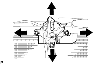
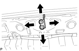
Adjust the hood lock.
-
Loosen the 3 bolts.
-
Adjust the hood lock and tighten the 3 bolts.
- Torque:
- 7.5 N*m { 76 kgf*cm, 66 in.*lbf }
-
Check that the striker can engage with the hood lock smoothly.
-
-
Install the radiator grille sub-assembly.
-
-
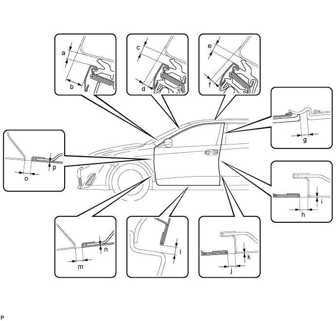
INSPECT FRONT DOOR
-
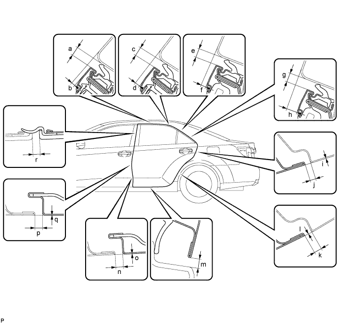
Check that the clearance measurements of areas a through p are within each standard range.
Reference Value Area Measurement Area Measurement *a 3.35 to 6.35 mm (0.132 to 0.250 in.) *b 9.0 to 12.0 mm (0.354 to 0.472 in.) *c 3.35 to 6.35 mm (0.132 to 0.250 in.) *d 1.7 to 4.7 mm (0.0669 to 0.185 in.) *e 3.35 to 6.35 mm (0.132 to 0.250 in.) *f 1.0 to 4.0 mm (0.0394 to 0.157 in.) *g 2.3 to 6.3 mm (0.0906 to 0.248 in.) *h 2.6 to 5.0 mm (0.102 to 0.197 in.) *i -1.2 to 1.2 mm (-0.0472 to 0.0472 in.) *j 2.6 to 5.0 mm (0.102 to 0.197 in.) *k -1.2 to 1.2 mm (-0.0472 to 0.0472 in.) *l 2.9 to 7.1 mm (0.114 to 0.280 in.) *m 2.3 to 4.7 mm (0.0906 to 0.185 in.) *n -1.2 to 1.2 mm (-0.0472 to 0.0472 in.) *o 2.3 to 4.7 mm (0.0906 to 0.185 in.) *p -1.2 to 1.2 mm (-0.0472 to 0.0472 in.) Tech Tips
-
Use the same procedure for the RH side and LH side.
-
The procedure listed below is for the LH side.
-
Centering bolts are used to mount the door hinge to the vehicle body and door. The door cannot be adjusted with the centering bolts installed. Substitute the centering bolts with standard bolts when making adjustments.
-
-
REMOVE FRONT WHEEL
-
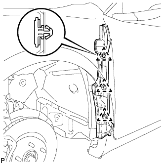
REMOVE FRONT FENDER SEAL
-
Disengage the 3 clips and remove the front fender seal.
-
-
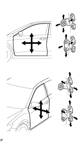
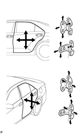
ADJUST FRONT DOOR
Note
Make sure to turn the power switch off when adjusting door lock strikers.
-
Using SST, loosen the hinge bolts on the vehicle body and adjust the door position.
- SST
- 09812-00010
-
Tighten the hinge bolts on the vehicle body after adjustment.
- Torque:
- 26 N*m { 265 kgf*cm, 19 ft.*lbf }
-
Loosen the hinge bolts on the door and adjust the door position.
-
Tighten the hinge bolts on the door after adjustment.
- Torque:
- 26 N*m { 265 kgf*cm, 19 ft.*lbf }
-
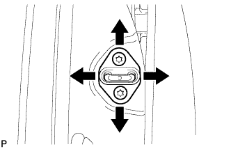
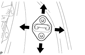
Using a T40 "TORX" socket wrench, slightly loosen the striker mounting screws.
-
Using a brass bar and a hammer, hit the striker to adjust its position.
-
Using a T40 "TORX" socket wrench, tighten the striker mounting screws after adjustment.
- Torque:
- 23 N*m { 235 kgf*cm, 17 ft.*lbf }
-
-
INSTALL FRONT FENDER SEAL
-
Install the front fender seal with new 3 clips.
-
-
INSTALL FRONT WHEEL
-
INSPECT REAR DOOR
-
Check that the clearance measurements of areas a through r are within each standard range.
Reference Value Area Measurement Area Measurement *a 3.35 to 6.35 mm (0.132 to 0.250 in.) *b 0.6 to 3.6 mm (0.0236 to 0.142 in.) *c 3.35 to 6.35 mm (0.132 to 0.250 in.) *d 0.9 to 3.9 mm (0.0354 to 0.154 in.) *e 3.35 to 6.35 mm (0.132 to 0.250 in.) *f 1.5 to 4.5 mm (0.0591 to 0.177 in.) *g 3.35 to 6.35 mm (0.132 to 0.250 in.) *h 5.4 to 8.4 mm (0.213 to 0.331 in.) *i -1.5 to 1.5 mm (-0.0591 to 0.0591 in.) *j 2.0 to 5.0 mm (0.0787 to 0.197 in.) *k 2.0 to 5.0 mm (0.0787 to 0.197 in.) *l -1.5 to 1.5 mm (-0.0591 to 0.0591 in.) *m 2.9 to 7.1 mm (0.114 to 0.280 in.) *n 2.6 to 5.0 mm (0.102 to 0.197 in.) *o -1.2 to 1.2 mm (-0.0472 to 0.0472 in.) *p 2.6 to 5.0 mm (0.102 to 0.197 in.) *q -1.2 to 1.2 mm (-0.0472 to 0.0472 in.) *r 2.3 to 6.3 mm (0.0906 to 0.248 in.) Tech Tips
-
Use the same procedure for the RH side and LH side.
-
The procedure listed below is for the LH side.
-
Centering bolts are used to mount the door hinge to the vehicle body and door. The door cannot be adjusted with the centering bolts installed. Substitute the centering bolts with standard bolts when making adjustments.
-
-
ADJUST REAR DOOR
Note
Make sure to turn the power switch off when adjusting door lock strikers.
-
Using SST, loosen the hinge bolts on the vehicle body and adjust the door position.
- SST
- 09812-00010
-
Tighten the hinge bolts on the vehicle body after the adjustment.
- Torque:
- 26 N*m { 265 kgf*cm, 19 ft.*lbf }
-
Loosen the hinge bolts on the door and adjust the door position.
-
Tighten the hinge bolts on the door after the adjustment.
- Torque:
- 26 N*m { 265 kgf*cm, 19 ft.*lbf }
-
Using a T40 "TORX" socket wrench, slightly loosen the striker mounting screws.
-
Using a brass bar and a hammer, hit the striker to adjust its position.
-
Using a T40 "TORX" socket wrench, tighten the striker mounting screws after adjustment.
- Torque:
- 23 N*m { 235 kgf*cm, 17 ft.*lbf }
-
-
INSPECT LUGGAGE COMPARTMENT DOOR
-
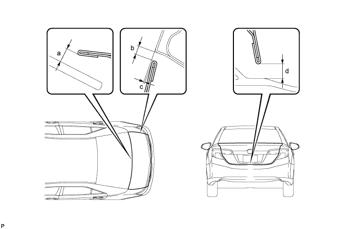
Check that the clearance measurements of areas a through d are within each standard range.
Reference Value Area Measurement Area Measurement *a 6.4 mm (0.252 in.) *b 2.0 to 5.0 mm (0.0787 to 0.197 in.) *c -1.0 to 2.0 mm (-0.0394 to 0.0787 in.) *d 3.85 to 7.85 mm (0.152 to 0.309 in.) Tech Tips
Centering bolts are used to mount the door hinge to the door. The door cannot be adjusted with the centering bolts installed. Substitute the centering bolts with standard bolts when making adjustments.
-
-
ADJUST LUGGAGE COMPARTMENT DOOR
-
Loosen the door side hinge bolts to adjust the door horizontally and vertically.
- Torque:
- 7.5 N*m { 76 kgf*cm, 66 in.*lbf }
-
Using a T40 "TORX" socket wrench, slightly loosen the striker mounting screws.
-
Using a brass bar and a hammer, hit the striker to adjust its position.
-
Using a T40 "TORX" socket wrench, tighten the striker mounting screws after adjustment.
- Torque:
- 23 N*m { 235 kgf*cm, 17 ft.*lbf }
-