BACK DOOR DISASSEMBLY

-
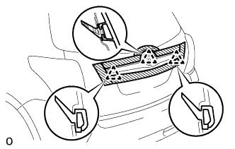
REMOVE CENTER BACK DOOR GARNISH
-
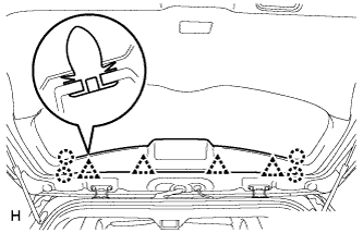
Detach the 4 clips and 4 claws, and remove the center back door garnish.
-
-
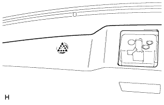
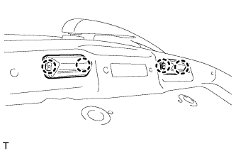
REMOVE CENTER STOP LIGHT ASSEMBLY
-
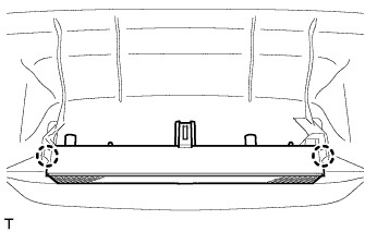
Detach the 2 claws and remove the stop light.
-
-
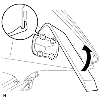
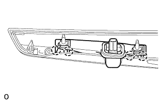
REMOVE BACK DOOR SIDE GARNISH LH
-
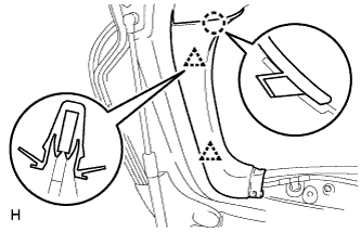
Detach the 2 clips and claw, and remove the back door side garnish.
-
-
REMOVE BACK DOOR SIDE GARNISH RH
-
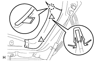
Detach the 2 clips and claw, and remove the back door side garnish.
-
-
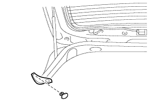
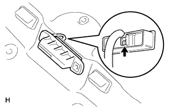
REMOVE BACK DOOR INSIDE HANDLE
-
Using moulding remover D, detach the 4 claws and remove the back door inside handle.
-
-
REMOVE BACK DOOR TRIM PANEL ASSEMBLY
-
Detach the clip.
-
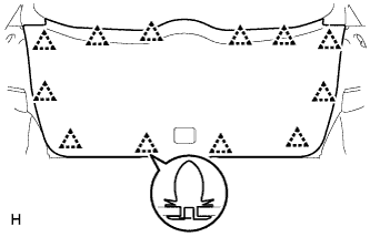
Detach the 12 clips and remove the back door trim board.
-
-
REMOVE NO. 2 BACK DOOR PANEL PROTECTOR
-
Remove the clip and No. 2 back door panel protector.
-
-
REMOVE NO. 1 BACK DOOR PANEL PROTECTOR
Tech Tips
Use the same procedure described for the No. 2 back door panel protector.
-
REMOVE REAR SPOILER SUB-ASSEMBLY
-
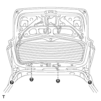
Remove the 4 nuts.
-
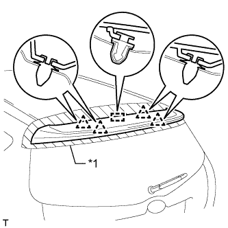
Text in Illustration *1 Protective Tape Put protective tape around the rear spoiler.
-
Detach the 4 clips and pin, and remove the rear spoiler.
-
-
REMOVE REAR WASHER NOZZLE
-
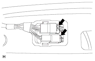
Disconnect the 2 connectors.
-
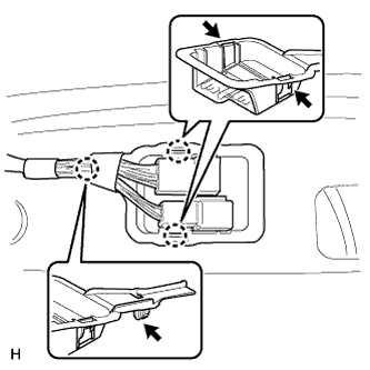
Detach the 3 claws and disconnect the connector holder.
-
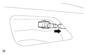
Disconnect the hose.
-
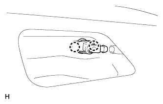
Detach the 2 claws and remove the washer nozzle.
-
-
REMOVE REAR WIPER ARM
-
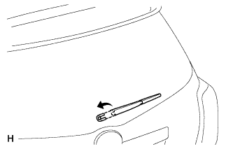
Open the wiper arm head cap.
-
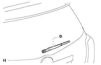
Remove the nut and rear wiper arm.
-
-
REMOVE REAR WIPER MOTOR AND BRACKET ASSEMBLY
-
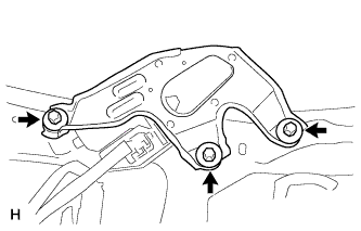
Disconnect the connector.
-
Remove the 3 bolts and rear wiper motor and bracket assembly.
-
-
REMOVE REAR WIPER MOTOR GROMMET
-
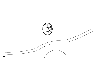
Remove the wiper motor grommet.
-
-
REMOVE BACK DOOR LOCK ASSEMBLY
-
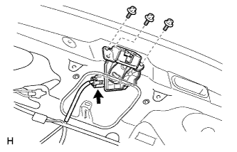
Remove the 3 bolts and back door lock assembly.
-
Disconnect the connector.
-
-
REMOVE BACK DOOR OUTSIDE GARNISH
-
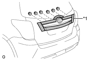
Text in Illustration *1 Protective Tape Put protective tape around the back door outside garnish.
-
Remove the 6 nuts.
-
Detach the 3 clips and remove the back door outside garnish.
Tech Tips
Detach the clip from the backside of the back door outside garnish.
-
-
REMOVE LICENSE PLATE LIGHT ASSEMBLY
-
Disconnect the 2 connectors.
-
Detach the 4 claws and remove the 2 lights.
-
-
REMOVE BACK DOOR OPENER SWITCH ASSEMBLY
-
Disconnect the connector and remove the back door opener switch.
-
-
REMOVE REAR TELEVISION CAMERA ASSEMBLY (w/ Rear View Monitor System)
-
Detach the 4 claws and remove the rear television camera assembly assembly.
-
-
REMOVE BACK DOOR STAY ASSEMBLY LH
-
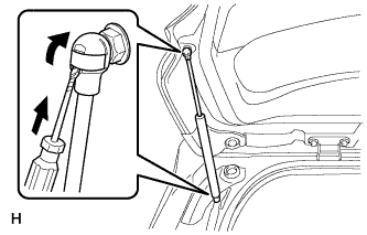
Text in Illustration *1 Protective Tape Using a screwdriver, remove the 2 stop rings as shown in the illustration, and then remove the back door stay.
CAUTION:
Remove the door stay while supporting the back door with one hand.
Tech Tips
Tape the screwdriver tip before use.
-
-
REMOVE BACK DOOR STAY ASSEMBLY RH
Tech Tips
Use the same procedure described for the LH side.
-
REMOVE UPPER BACK DOOR DAMPER STAY BRACKET LH
-
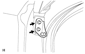
Remove the 2 bolts and upper back door damper stay bracket.
-
-
REMOVE UPPER BACK DOOR DAMPER STAY BRACKET RH
Tech Tips
Use the same procedure described for the LH side.
-
REMOVE BACK DOOR STAY BOLT (for LH Side)
-
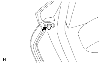
Remove the back door stay bolt.
-
-
REMOVE BACK DOOR STAY BOLT (for RH Side)
Tech Tips
Use the same procedure described for the LH side.