HOOD LOCK CONTROL CABLE ASSEMBLY INSTALLATION

Tech Tips
-
Use the same procedure for LHD and RHD vehicles.
-
The procedure listed below is for LHD vehicles.
-
A bolt without a torque specification is shown in the standard bolt chart Click here.
-
INSTALL HOOD LOCK CONTROL CABLE ASSEMBLY (for LHD)
-
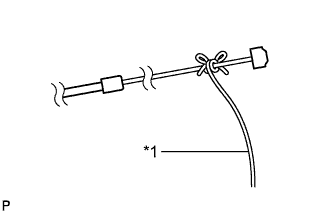
Text in Illustration *1 String Tie the string that was passed through the engine compartment to the end of the hood lock control cable assembly as shown in the illustration.
-
Pull the string until the hood lock control cable grommet contacts the dash panel, and then connect the clamps shown in the illustration to install the cable.
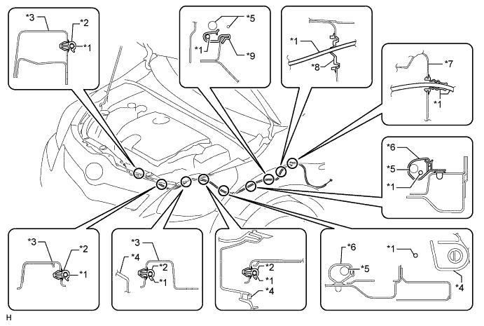
Text in Illustration *1 Hood Lock Control Cable Assembly *2 Clamp *3 Radiator Support Side *4 Headlight *5 Wire Harness *6 Wire Harness Clamp *7 Dash Panel *8 Grommet *9 Hood Lock Control Cable Clamp - -
-
-
INSTALL HOOD LOCK CONTROL CABLE ASSEMBLY (for RHD)
-
Text in Illustration *1 String Tie the string that was passed through the engine compartment to the end of the hood lock control cable assembly as shown in the illustration.
-
Pull the string until the hood lock control cable grommet contacts the dash panel, and then connect the clamps shown in the illustration to install the cable.
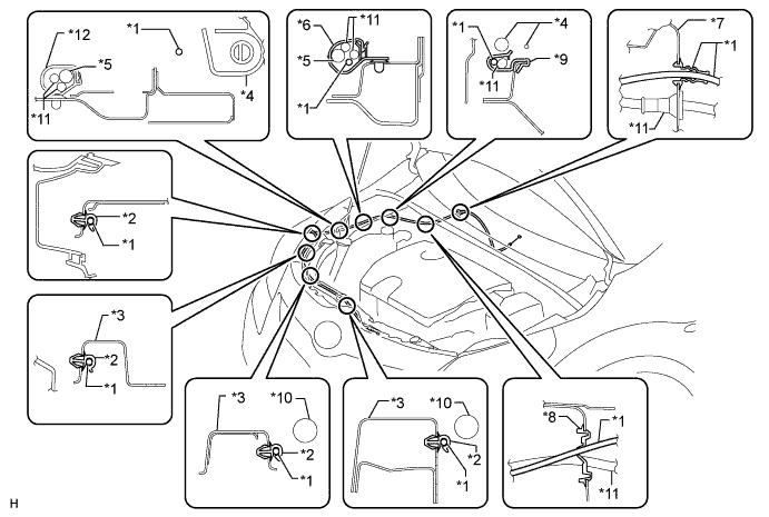
Text in Illustration *1 Hood Lock Control Cable Assembly *2 Clamp *3 Radiator Support Side *4 Headlight *5 Wire Harness *6 Wire Harness Clamp *7 Dash Panel *8 Grommet *9 Hood Lock Control Cable Clamp 10 Radiator Hose *11 Washer Hose *12 Washer Hose Clamp
-
-
INSTALL HOOD LOCK CONTROL LEVER SUB-ASSEMBLY
-
Connect the hood lock control cable assembly.
-
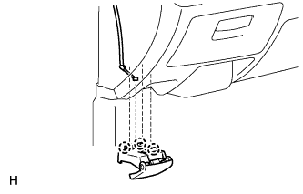
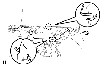
Attach the 3 claws to install the hood lock control lever sub-assembly.
Note
Make sure the cable inside the cabin does not interfere with the clutch pedal, link or accelerator pedal.
-
-
INSTALL NO. 1 INSTRUMENT PANEL UNDER COVER SUB-ASSEMBLY
-
Attach the claw and guide to install the No. 1 instrument panel under cover.
-
Install the 2 screws <A>.
-
-
INSTALL HOOD LOCK ASSEMBLY
-
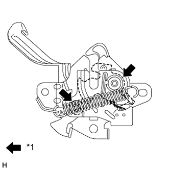
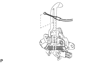
Text in Illustration *1 MP grease Apply MP grease to the sliding areas of the lock.
-
for LHD:
-
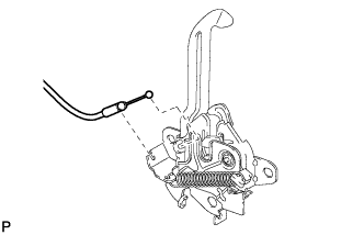
Connect the hood lock control cable.
-
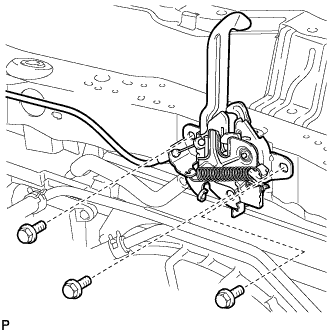
Install the hood lock with the 3 bolts.
- Torque:
- 7.5 N*m { 76 kgf*cm, 66 in.*lbf }
-
-
for RHD:
-
Connect the hood lock control cable.
-
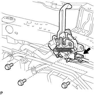
Connect the connector.
-
Install the hood lock with the 3 bolts.
- Torque:
- 7.5 N*m { 76 kgf*cm, 66 in.*lbf }
-
-
-
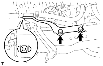
INSTALL NO. 1 WATER HOSE CLAMP BRACKET
-
Attach the 2 claws and install the water hose clamp bracket to the upper radiator support with the 2 bolts.
- Torque:
- 5.0 N*m { 51 kgf*cm, 44 in.*lbf }
-
-
INSTALL FRONT FENDER LINER LH
-
Install the front fender liner Click here.
-
-
INSTALL RADIATOR SUPPORT OPENING COVER
-
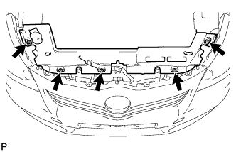
Install the radiator support opening cover with the 5 clips.
-
-
CONNECT CABLE TO NEGATIVE BATTERY TERMINAL
Note
When disconnecting the cable, some systems need to be initialized after the cable is reconnected Click here.
-
INSTALL BATTERY SERVICE HOLE COVER
-
Install the battery service hole cover with the clip.
-