WINDOW DEFOGGER SYSTEM TERMINALS OF ECU

-
CHECK HEATER CONTROL SUB-ASSEMBLY (for Manual Air Conditioning System)

-
Disconnect the H65 heater control connector.
-
Measure the voltage and resistance according to the value(s) in the table below.
Terminal No. (Symbol) Wiring Color Terminal Description Condition Specified Condition H65-3 (IG+) - H65-5 (E) Y - W-B Power source (IG) Ignition switch ON 11 to 14 V H65-3 (IG+) - H65-5 (E) Ignition switch off Below 1 V H65-5 (E) - Body ground W-B - Body ground Ground Always Below 1 Ω
-
If the result is not as specified, there may be a malfunction in the wire harness.
-
-
Reconnect the H65 heater control connector.
-
Measure the voltage according to the value(s) in the table below.
Terminal No. (Symbol) Wiring Color Terminal Description Condition Specified Condition H65-2 (RDEF) - H65-5 (E) B - W-B Rear defogger signal Ignition switch ON, rear window defogger switch off 11 to 14 V H65-2 (RDEF) - H65-5 (E) Ignition switch ON, rear window defogger switch on Below 1 V
-
If the result is not as specified, there may be a malfunction in the heater control.
-
-
-
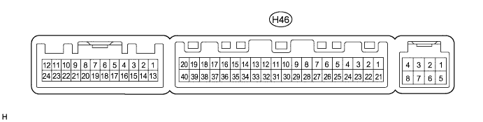
CHECK AIR CONDITIONING AMPLIFIER ASSEMBLY
-
Disconnect the H46 air conditioning amplifier connector.
-
Measure the voltage and resistance according to the value(s) in the table below.
Terminal No. (Symbol) Wiring Color Terminal Description Condition Specified Condition H46-1 (IG+) - H46-14 (GND) Y - W-B Power source (IG) Ignition switch ON 11 to 14 V H46-1 (IG+) - H46-14 (GND) Ignition switch off Below 1 V H46-21 (B) - H46-14 (GND) W - W-B Power source (Back-up) Always 11 to 14 V H46-14 (GND) - Body ground W-B - Body ground Ground Always Below 1 Ω
-
If the result is not as specified, there may be a malfunction in the wire harness.
-
-
Reconnect the H46 air conditioning amplifier connector.
-
Measure the voltage according to the value(s) in the table below.
Terminal No. (Symbol) Wiring Color Terminal Description Condition Specified Condition H46-38 (RDFG) - H46-14 (GND) B - W-B Rear defogger signal Ignition switch ON, rear window defogger switch off 11 to 14 V H46-38 (RDFG) - H46-14 (GND) Ignition switch ON, rear window defogger switch on Below 1 V
-
If the result is not as specified, there may be a malfunction in the air conditioning amplifier.
-
-
-
CHECK AIR CONDITIONING CONTROL ASSEMBLY (for Automatic Air Conditioning System)

-
Disconnect the H21 air conditioning control connector.
-
Measure the voltage and resistance according to the value(s) in the table below.
Terminal No. (Symbol) Wiring Color Terminal Description Condition Specified Condition H21-2 (IG+) - H21-5 (GND) R - BR Power source (IG) Ignition switch ON 11 to 14 V H21-2 (IG+) - H21-5 (GND) Ignition switch off Below 1 V H21-5 (GND) - Body ground BR - Body ground Ground Always Below 1 Ω
-
If the result is not as specified, there may be a malfunction in the wire harness.
-
-
-
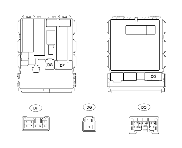
CHECK MAIN BODY ECU (INSTRUMENT PANEL JUNCTION BLOCK ASSEMBLY)
-
Disconnect the DG main body ECU connector.
-
Measure the voltage according to the value(s) in the table below.
Terminal No. (Symbol) Wiring Color Terminal Description Condition Specified Condition DG-1 - Body ground W - Body ground Power source Always 11 to 14 V
-
If the result is not as specified, there may be a malfunction in the wire harness.
-
-
Reconnect the DG main body ECU connector.
-
Measure the voltage according to the value(s) in the table below.
Terminal No. (Symbol) Wiring Color Terminal Description Condition Specified Condition DQ-12 - Body ground B - Body ground DEF relay operation signal Ignition switch ON, rear window defogger switch off 11 to 14 V DQ-12 - Body ground Ignition switch ON, rear window defogger switch on Below 1 V DF-2 - Body ground B - Body ground Defogger wire operation signal Ignition switch ON, rear window defogger switch off Below 1 V DF-2 - Body ground Ignition switch ON, rear window defogger switch on 11 to 14 V
-
If the result is not as specified, there may be a malfunction in the main body ECU.
-
-