POWER WINDOW REGULATOR MOTOR (for Front Door) INSTALLATION

Tech Tips
-
Use the same procedure for the RH and LH sides.
-
The procedure listed below is for the LH side.
-
A bolt without a torque specification is shown in the standard bolt chart Click here.
-
INSTALL FRONT DOOR WINDOW REGULATOR ASSEMBLY LH
-
Apply MP grease to the sliding and rotating areas of the window regulator.
-
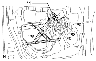
Text in Illustration *1 Temporary Bolt Temporarily install the temporary bolt onto the window regulator.
-
Insert the window regulator into the door panel. Use the temporary bolt to hang the window regulator on the door panel.
Note
Be careful not to drop the window regulator as it may become damaged.
-
Temporarily install the window regulator with the 5 bolts.
-
Tighten the 6 bolts.
- Torque:
- 8.0 N*m { 82 kgf*cm, 71 in.*lbf }
-
Connect the connector.
-
-
INSTALL FRONT DOOR GLASS SUB-ASSEMBLY LH
-
for Driver Side:
Temporarily install the master switch assembly.
-
for Front Passenger Side:
Temporarily install the regulator switch assembly.
-
Connect the cable to the negative (-) battery terminal.
-
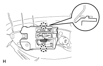
Move the door glass until the bolts appear in the service holes.
-
Disconnect the cable from the negative (-) battery terminal.
Note
When disconnecting the cable, some systems need to be initialized after the cable is reconnected Click here.
-
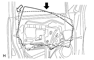
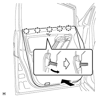
Insert the door glass into the door panel along the glass run as indicated by the arrows in the illustration.
Note
Be careful not to damage the glass.
-
Install the door glass to the window regulator with the 2 bolts.
- Torque:
- 8.0 N*m { 82 kgf*cm, 71 in.*lbf }
-
-
INSTALL FRONT DOOR SERVICE HOLE COVER LH
-
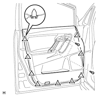
Apply butyl tape to the door.
-
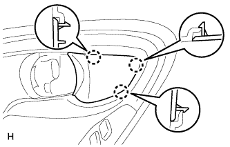
Pass the front door lock remote control cable and front door inside locking cable through a new front door service hole cover.
-
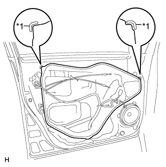
Text in Illustration *1 Reference Point Install the front door service hole cover according to the reference points on the front door panel.
Note
-
Securely install the front door service hole cover to prevent wrinkles and air bubbles.
-
There should be no wrinkles or folds after installing the service hole cover.
-
After installing the service hole cover, check the seal quality.
-
-
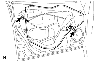
Connect the 2 connectors.
-
-
INSTALL FRONT DOOR INNER GLASS WEATHERSTRIP LH
-
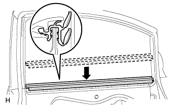
Install the front door inner glass weatherstrip.
-
-
INSTALL FRONT DOOR INSIDE HANDLE SUB-ASSEMBLY LH
-
Attach the 3 claws to install the inside handle bezel.
-
-
INSTALL FRONT DOOR TRIM BOARD SUB-ASSEMBLY LH
-
Attach the 2 claws to install the front door inside handle sub-assembly to the door trim board.
-
Attach the front door trim board with the 5 claws of the front door inner glass weatherstrip and the reference boss.
-
w/ Courtesy Light:
-
Connect the courtesy light connector.
-
-
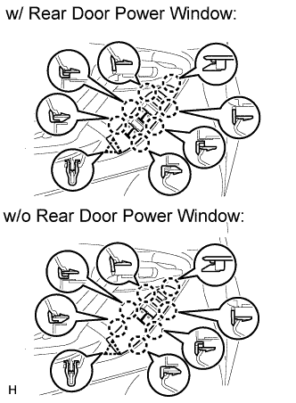
Attach the 9 clips to install the trim board.
-
Install the 3 screws.
-
-
INSTALL POWER WINDOW REGULATOR MASTER SWITCH ASSEMBLY WITH FRONT DOOR ARMREST BASE PANEL
-
Connect the connector.
-
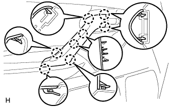
Attach the 7 claws and clip to install the power window regulator master switch assembly with front door armrest base panel.
-
-
INSTALL POWER WINDOW REGULATOR SWITCH ASSEMBLY WITH FRONT DOOR ARMREST BASE PANEL (for Front Passenger Side)
Tech Tips
Use the same procedure described for the driver side.
-
INSTALL FRONT DOOR TRIM MOULDING LH
-
Attach the 8 claws to install the front door trim moulding.
-
-
INSTALL FRONT DOOR INSIDE HANDLE BEZEL LH
-
Attach the 3 claws to install the inside handle bezel.
-
-
CONNECT CABLE TO NEGATIVE BATTERY TERMINAL
Note
When disconnecting the cable, some systems need to be initialized after the cable is reconnected Click here.