POWER WINDOW CONTROL SYSTEM Driver Side Power Window does not Operate with Power Window Master Switch
DESCRIPTION
-
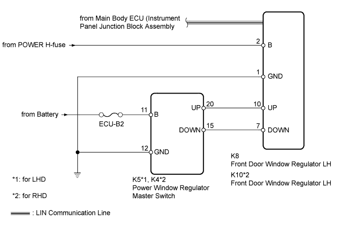
If the manual up/down function does not operate, there may be a malfunction in the power window regulator master switch, door window regulator, harness or connector.
WIRING DIAGRAM
INSPECTION PROCEDURE
Note
Inspect the fuses for circuits related to this system before performing the following inspection procedure.
PROCEDURE
-
CHECK LIN COMMUNICATION SYSTEM
-
Check for LIN communication system DTCs related to the power window control system Click here.
OK LIN communication system DTCs are not output.
NG 
GO TO LIN COMMUNICATION SYSTEM Click here
OK 
-
-
CHECK FOR DTC (B2312)
-
Check if DTC B2312 is output Click here.
OK DTC B2312 is not output.
NG
GO TO DTC B2312 Click here
OK
-
-
READ VALUE USING INTELLIGENT TESTER (POWER WINDOW REGULATOR MASTER SWITCH ASSEMBLY)
-
Use the Data List to check if the power window regulator master switch is functioning properly Click here.
D-Door Motor Tester Display Measurement Item/Range Normal Condition Diagnostic Note D Door P/W Up SW Driver side power window manual up signal / ON or OFF ON: Driver side power window manual up switch operated
OFF: Driver side power window switch not operated
- D Door P/W Down SW Driver side power window manual down signal / ON or OFF ON: Driver side power window manual down switch operated
OFF: Driver side power window switch not operated
- OK The display changes according to operation of the power window regulator master switch. Result Result Proceed to OK (for LHD) A OK (for RHD) B NG C
B
REPLACE FRONT DOOR WINDOW REGULATOR ASSEMBLY RH Click here
C 
CHECK HARNESS AND CONNECTOR (POWER WINDOW REGULATOR MASTER SWITCH ASSEMBLY - BATTERY AND BODY GROUND) Click here
A 
REPLACE FRONT DOOR WINDOW REGULATOR ASSEMBLY LH Click here
-
-
CHECK HARNESS AND CONNECTOR (POWER WINDOW REGULATOR MASTER SWITCH ASSEMBLY - BATTERY AND BODY GROUND)
-
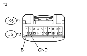
Text in Illustration *1 for LHD *2 for RHD *3 Front view of wire harness connector
(to Power Window Regulator Master Switch)
Disconnect the K5*1 or J5*2 switch connector.
-
*1: for LHD
-
*2: for RHD
-
-
Measure the voltage and resistance according to the value(s) in the table below.
Standard Voltage for LHD Tester Connection Condition Specified Condition K5-11 (B) - Body ground Always 11 to 14 V for RHD Tester Connection Condition Specified Condition J5-11 (B) - Body ground Always 11 to 14 V Standard Resistance for LHD Tester Connection Condition Specified Condition K5-12 (GND) - Body ground Always Below 1 Ω for RHD Tester Connection Condition Specified Condition J5-12 (GND) - Body ground Always Below 1 Ω
NG
REPAIR OR REPLACE HARNESS OR CONNECTOR
OK
-
-
CHECK HARNESS AND CONNECTOR (FRONT DOOR WINDOW REGULATOR ASSEMBLY - BATTERY AND BODY GROUND)
-
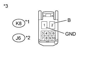
Text in Illustration *1 for LHD *2 for RHD *3 Front view of wire harness connector
(to Front Door Window Regulator)
Disconnect the K8*1 or J6*2 regulator connector.
-
*1: for LHD
-
*2: for RHD
-
-
Measure the voltage and resistance according to the value(s) in the table below.
Standard Voltage for LHD Tester Connection Condition Specified Condition K8-2 (B) - Body ground Always 11 to 14 V for RHD Tester Connection Condition Specified Condition J6-2 (B) - Body ground Always 11 to 14 V Standard Resistance for LHD Tester Connection Condition Specified Condition K8-1 (GND) - Body ground Always Below 1 Ω for RHD Tester Connection Condition Specified Condition J6-1 (GND) - Body ground Always Below 1 Ω
NG
REPAIR OR REPLACE HARNESS OR CONNECTOR
OK
-
-
CHECK HARNESS AND CONNECTOR (POWER WINDOW REGULATOR MASTER SWITCH ASSEMBLY - FRONT DOOR WINDOW REGULATOR ASSEMBLY)
-
*1: for LHD
-
*2: for RHD
-
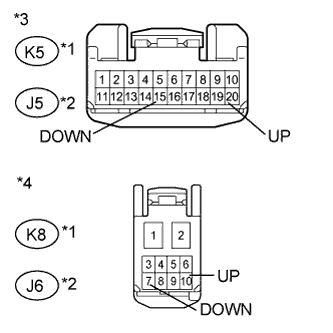
Text in Illustration *1 for LHD *2 for RHD *3 Front view of wire harness connector
(to Power Window Regulator Master Switch)
*4 Front view of wire harness connector
(to Front Door Window Regulator)
Disconnect the K5*1 or J5*2 switch connector.
-
Disconnect the K8*1 or J6*2 regulator connector.
-
Measure the resistance according to the value(s) in the table below.
Standard Resistance for LHD Tester Connection Condition Specified Condition K5-20 (UP) - K8-10 (UP) Always Below 1 Ω K5-15 (DOWN) - K8-7 (DOWN) Always Below 1 Ω K5-20 (UP) or K8-10 (UP) - Body ground Always 10 kΩ or higher K5-15 (DOWN) or K8-7 (DOWN) - Body ground Always 10 kΩ or higher for RHD Tester Connection Condition Specified Condition J5-20 (UP) - J6-10 (UP) Always Below 1 Ω J5-15 (DOWN) - J6-7 (DOWN) Always Below 1 Ω J5-20 (UP) or J6-10 (UP) - Body ground Always 10 kΩ or higher J5-15 (DOWN) or J6-7 (DOWN) - Body ground Always 10 kΩ or higher Result Result Proceed to OK (for LHD) A OK (for RHD) B NG C
B
INSPECT FRONT DOOR WINDOW REGULATOR ASSEMBLY RH Click here
C
REPAIR OR REPLACE HARNESS OR CONNECTOR
A
-
-
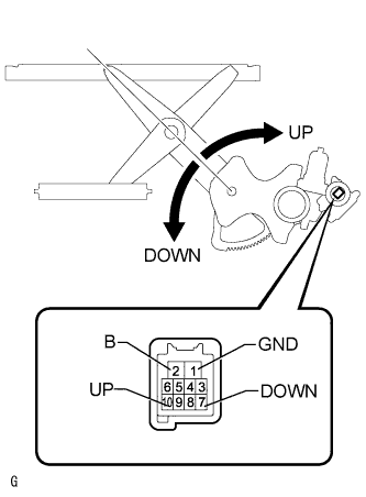
INSPECT FRONT DOOR WINDOW REGULATOR ASSEMBLY LH
-
Remove the door window regulator Click here.
-
Check that the window regulator moves smoothly as follows.
Note
-
Do not apply positive (+) battery voltage to any terminal other than terminal 2 (B) to avoid damaging the pulse sensor inside the motor.
-
Reset the door window regulator (initialize the pulse sensor) after installing the door window regulator to the door.
OK Measurement Condition Specified Condition
-
Connect the positive (+) battery terminal to terminal 2 (B), and connect the negative (-) battery terminal to terminal 1 (GND), and keep them connected for 3 seconds or more.
-
With terminals 2 (B) and 1 (GND) connected to the battery, connect the negative (-) battery terminal to terminal 10 (UP).
-
Disconnect and reconnect the negative (-) battery terminal to terminal 10 (UP) within 1 second.
Arm of window regulator rotates clockwise (Up)
-
Connect the positive (+) battery terminal to terminal 2 (B), and connect the negative (-) battery terminal to terminal 1 (GND), and keep them connected for 3 seconds or more.
-
With terminals 2 (B) and 1 (GND) connected to the battery, connect the negative (-) battery terminal to terminal 7 (DOWN).
-
Disconnect and reconnect the negative (-) battery terminal to terminal 7 (DOWN) within 1 second.
Arm of window regulator rotates counterclockwise (Down) -
NG
REPLACE FRONT DOOR WINDOW REGULATOR ASSEMBLY LH Click here
OK
REPLACE POWER WINDOW REGULATOR MASTER SWITCH ASSEMBLY Click here
-
-
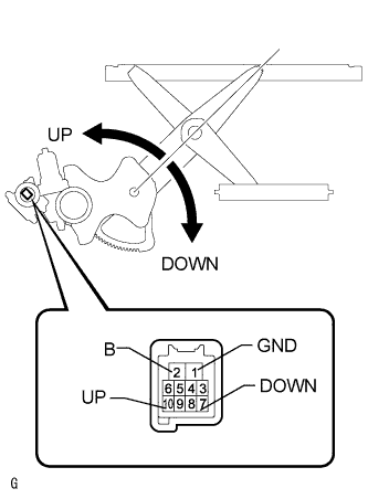
INSPECT FRONT DOOR WINDOW REGULATOR ASSEMBLY RH
-
Remove the door window regulator Click here.
-
Check that the window regulator moves smoothly as follows.
Note
-
Do not apply positive (+) battery voltage to any terminal other than terminal 2 (B) to avoid damaging the pulse sensor inside the motor.
-
Reset the door window regulator (initialize the pulse sensor) after installing the door window regulator to the door.
OK Measurement Condition Specified Condition
-
Connect the positive (+) battery terminal to terminal 2 (B), and connect the negative (-) battery terminal to terminal 1 (GND), and keep them connected for 3 seconds or more.
-
With terminals 2 (B) and 1 (GND) connected to the battery, connect the negative (-) battery terminal to terminal 10 (UP).
-
Disconnect and reconnect the negative (-) battery terminal to terminal 10 (UP) within 1 second.
Arm of window regulator rotates counterclockwise (Up)
-
Connect the positive (+) battery terminal to terminal 2 (B), and connect the negative (-) battery terminal to terminal 1 (GND), and keep them connected for 3 seconds or more.
-
With terminals 2 (B) and 1 (GND) connected to the battery, connect the negative (-) battery terminal to terminal 7 (DOWN).
-
Disconnect and reconnect the negative (-) battery terminal to terminal 7 (DOWN) within 1 second.
Arm of window regulator rotates clockwise (Down) -
NG
REPLACE FRONT DOOR WINDOW REGULATOR ASSEMBLY RH Click here
OK
REPLACE POWER WINDOW REGULATOR MASTER SWITCH ASSEMBLY Click here
-