ROOF HEADLINING REASSEMBLY

-
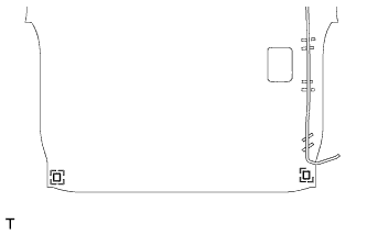
INSTALL NO. 2 ANTENNA CORD SUB-ASSEMBLY
-
w/o Roof Sunshade System:
-
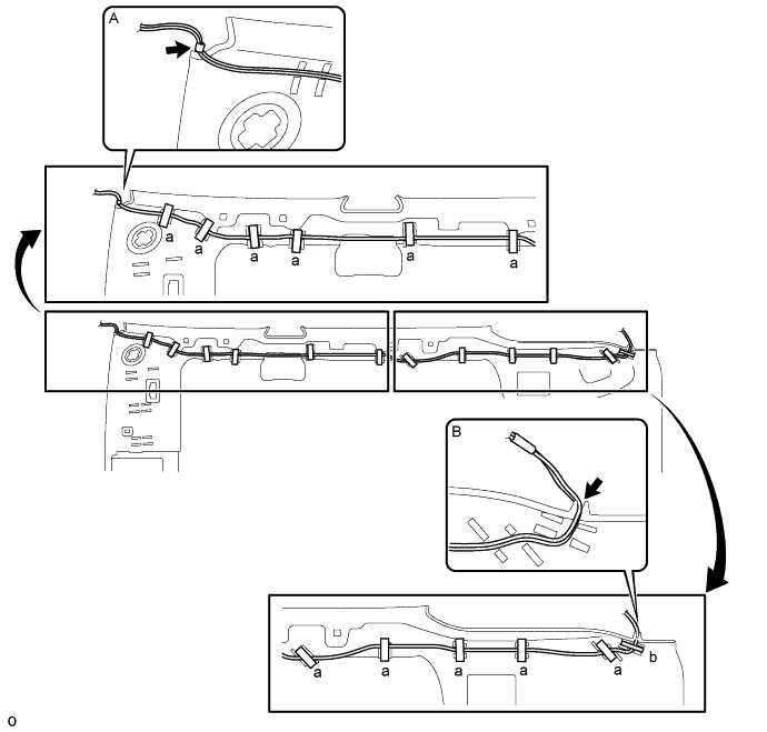
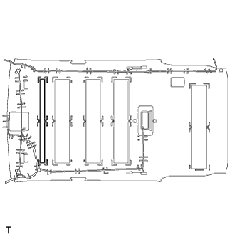
Align the marking tape on the antenna cord with the roof headlining tab shown in the part of the illustration labeled A, and wrap tape around the cord to install it.
-
Starting from the front of the vehicle, attach the antenna cord to the roof headlining with tape at the 11 marked locations labeled "a".
-
While adjusting the slack of the antenna cord, attach the antenna cord to the roof headlining with tape at the marked location labeled "b".
-
Set the antenna cord into the cutout of the roof headlining as shown in the part of the illustration labeled B.
-
-
w/ Roof Sunshade System:
-
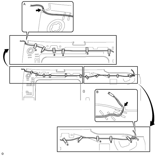
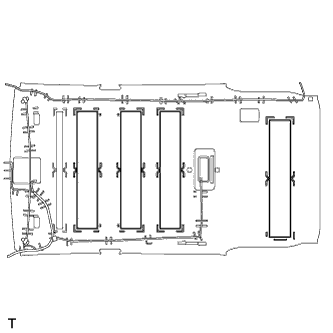
Align the marking tape on the antenna cord with the roof headlining tab shown in the part of the illustration labeled A, and wrap tape around the cord to install it.
-
Starting from the front of the vehicle, attach the antenna cord to the roof headlining with tape at the 11 marked locations labeled "a".
-
While adjusting the slack of the antenna cord, attach the antenna cord to the roof headlining with tape at the marked location labeled "b".
-
Set the antenna cord into the cutout of the roof headlining as shown in the part of the illustration labeled B.
-
-
-
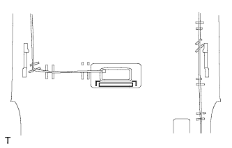
INSTALL NO. 1 ROOF WIRE
-
w/o Roof Sunshade System:
-
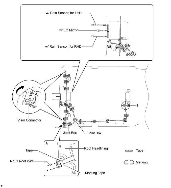
Fix the No. 1 roof wire in place by wrapping tape around the No. 1 roof wire and the protrusion of the roof headlining as shown in the part of the illustration labeled A.
-
Position the joint boxes as shown in the illustration and set the No. 1 roof wire on the roof headlining.
-
Attach tape at the locations shown in the illustration to install the No. 1 roof wire.
Tech Tips
-
Attach the tape in the part of the illustration labeled B while adjusting the slack of the No. 1 roof wire.
-
Apply sufficient pressure when placing tape.
-
-
Turn the visor connectors approximately 90° clockwise to install them to the roof headlining.
-
-
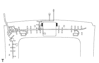
w/ Roof Sunshade System:
-
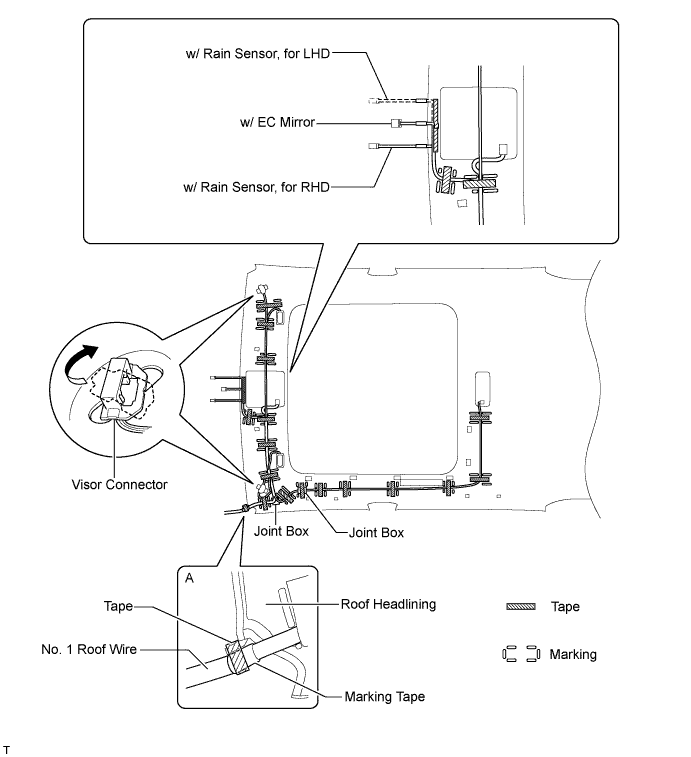
Fix the No. 1 roof wire in place by wrapping tape around the No. 1 roof wire and the protrusion of the roof headlining as shown in the part of the illustration labeled A.
-
Position the joint boxes as shown in the illustration and set the No. 1 roof wire on the roof headlining.
-
Attach tape at the locations shown in the illustration to install the No. 1 roof wire.
Tech Tips
Apply sufficient pressure when placing tape.
-
Turn the visor connectors approximately 90° clockwise to install them to the roof headlining.
-
-
-
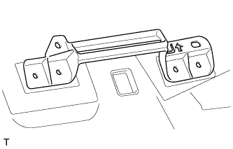
INSTALL HEADLINING SUPPORT RETAINER
Tech Tips
Use the same procedure to install the headlining support retainer on the other side.
-
Align the headlining support retainer with the markings on the roof headlining and install the headlining support retainer to the position shown in the illustration using hot-melt glue or double-sided tape.
-
-
INSTALL ROOF HEADLINING PAD END
-
Align the 2 roof headlining pads end with the markings on the roof headlining and install the 2 roof headlining pad ends to the position shown in the illustration using hot-melt glue or double-sided tape.
-
-
INSTALL ROOF HEADLINING PAD
-
Align the roof headlining pad with the markings on the roof headlining and install the roof headlining pad to the position shown in the illustration using hot-melt glue or double-sided tape.
-
-
INSTALL NO. 2 ROOF HEADLINING PAD (w/ Roof Sunshade System)
-
Align the 2 No. 2 roof headlining pads with the markings on the roof headlining and install the 2 No. 2 roof headlining pads to the position shown in the illustration using hot-melt glue or double-sided tape.
-
-
INSTALL NO. 2 ROOF SILENCER PAD (w/o Roof Sunshade System)
-
Align the No. 2 roof silencer pad with the markings on the roof headlining and install the No. 2 roof silencer pad to the position shown in the illustration using hot-melt glue or double-sided tape.
-
-
INSTALL NO. 1 ROOF SILENCER PAD (w/o Roof Sunshade System)
-
Align the 4 No. 1 roof silencer pads with the markings on the roof headlining and install the 4 No. 1 roof silencer pads to the position shown in the illustration using hot-melt glue or double-sided tape.
-
-
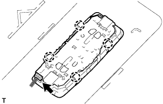
INSTALL VANITY LIGHT ASSEMBLY
Tech Tips
Use the same procedure to install the vanity light on the other side.
-
Attach the 3 claws to install the vanity light.
-
-
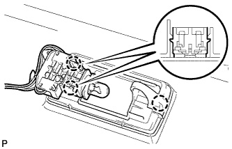
INSTALL NO. 1 ROOM LIGHT ASSEMBLY
-
Attach the 4 claws to install the No. 1 room light.
-
Connect the connector.
-