UPPER INSTRUMENT PANEL INSTALLATION

Tech Tips
-
Use the same procedure for RHD and LHD vehicles.
-
The procedure listed below is for LHD vehicles.
-
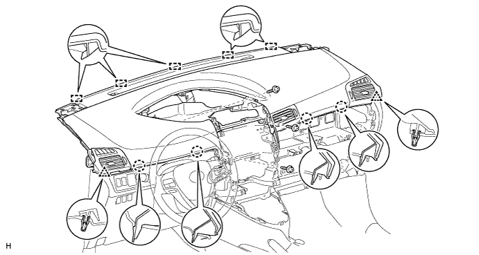
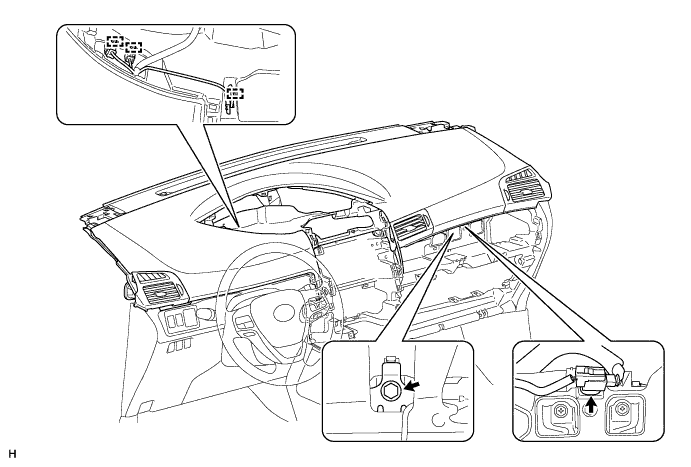
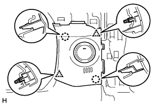
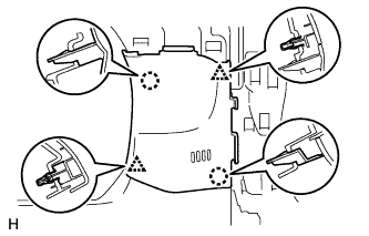
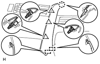
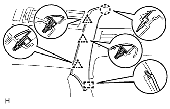
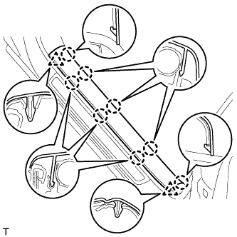
INSTALL INSTRUMENT PANEL SAFETY PAD SUB-ASSEMBLY
-
Securely attach the 5 guides, 4 claws and 2 clips of the instrument panel safety pad to the vehicle body.
-
Install the instrument panel safety pad with the 3 screws <B>.
-
Install the passenger airbag bolt <A>.
- Torque:
- 20 N*m { 204 kgf*cm, 15 ft.*lbf }
-
Connect the connector and clamps.
-
-
INSTALL NO. 1 INSTRUMENT PANEL SPEAKER PANEL SUB-ASSEMBLY
-
for 4 Speakers:
-
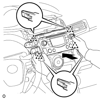
Set the 2 claws on the side of the No. 1 instrument panel speaker panel towards the front of the vehicle in place and using them as pivot points, lower the No. 1 instrument panel speaker panel in the direction indicated by the arrow in the illustration, and then attach the claws and clips to the instrument panel to install the No. 1 instrument panel speaker panel.
-
-
for 6 Speakers:
-
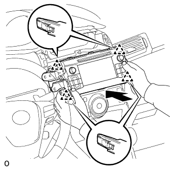
Connect the speaker connector.
-
Set the 2 claws on the side of the No. 1 instrument panel speaker panel towards the front of the vehicle in place and using them as pivot points, lower the No. 1 instrument panel speaker panel in the direction indicated by the arrow in the illustration, and then attach the claws and clips to the instrument panel to install the No. 1 instrument panel speaker panel.
-
-
-
INSTALL NO. 2 INSTRUMENT PANEL SPEAKER PANEL SUB-ASSEMBLY
Tech Tips
Use the same procedure described for the No. 1 instrument panel speaker panel.
-
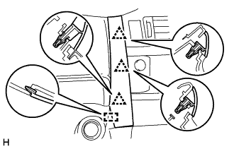
INSTALL NO. 1 SWITCH HOLE BASE
-
w/ Entry and Start System:
-
Connect the connector.
-
Attach the 2 claws and 2 clips to install the No. 1 switch hole base.
-
-
w/o Entry and Start System:
-
Attach the 2 claws and 2 clips to install the No. 1 switch hole base.
-
-
-
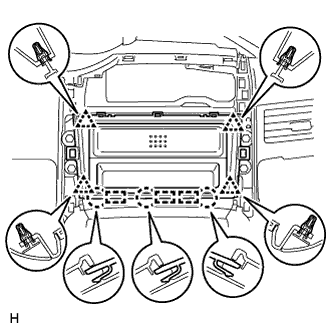
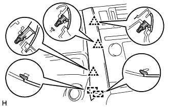
INSTALL NO. 2 SWITCH HOLE BASE
-
for LHD:
Attach the 5 claws and 5 clips to install the No. 2 switch hole base.
-
for RHD:
Attach the 3 claws and 5 clips to install the No. 2 switch hole base.
-
-
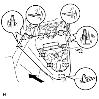
INSTALL LOWER CENTER INSTRUMENT PANEL FINISH PANEL (for Manual Transaxle)
-
for Automatic Air Conditioning System:
-
Attach the 2 claws, 4 clips and 5 guides to install the lower center instrument panel finish panel.
-
Install the 2 screws <C>.
-
-
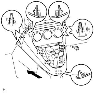
for Manual Air Conditioning System:
-
Attach the 4 clips, 2 claws and 5 guides to install the lower center instrument panel finish panel.
-
Install the 2 screws <C>.
-
-
-
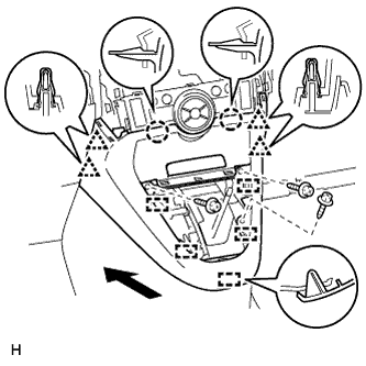
INSTALL LOWER CENTER INSTRUMENT PANEL FINISH PANEL (except Manual Transaxle)
-
for Automatic Air Conditioning System:
-
Attach the 2 claws, 4 clips and 5 guides to install the lower center instrument panel finish panel.
-
Install the 3 screws <C>.
-
-
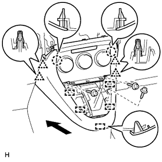
for Manual Air Conditioning System:
-
Attach the 4 clips, 2 claws and 5 guides to install the lower center instrument panel finish panel.
-
Install the 3 screws <C>.
-
-
-
INSTALL SHIFTING HOLE COVER (for Manual Transaxle)
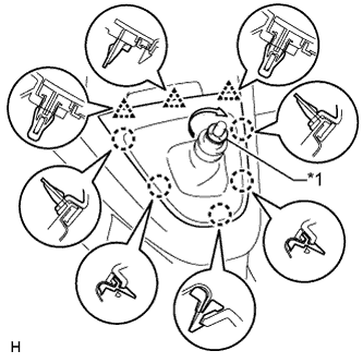
Text in Illustration *1 T Washer
-
Attach the 5 claws and 3 clips to install the shifting hole cover.
-
Install the knob spring.
-
Install the T washer and twist it in the direction indicated by the arrow.
-
-
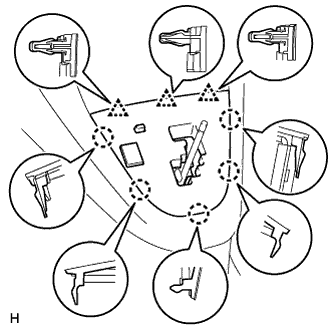
INSTALL POSITION INDICATOR HOUSING ASSEMBLY (except Manual Transaxle)
-
Connect the connector.
-
Attach the 5 claws and 3 clips to install the position indicator housing.
-
-
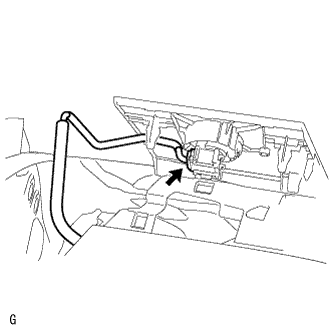
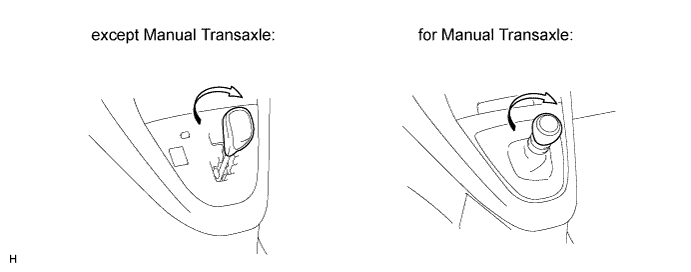
INSTALL SHIFT LEVER KNOB SUB-ASSEMBLY
-
Install the shift lever knob and twist it in the direction indicated by the arrow.
-
-
INSTALL STEREO OPENING COVER WITH BRACKET (w/o Audio)
-
Install the stereo opening cover with the 4 bolts.
-
-
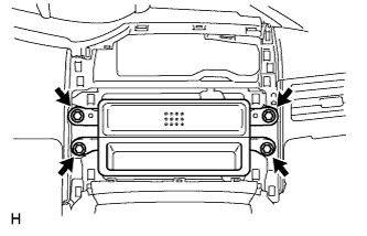
INSTALL RADIO RECEIVER ASSEMBLY (for Radio Receiver Type)
-
Connect the connectors.
-
Insert the radio receiver assembly with bracket to attach the 4 clips on its backside.
Note
When inserting the radio receiver, do not press the knobs on it.
-
Install the radio receiver assembly with bracket with the 4 screws.
- Torque:
- 4.0 N*m { 40 kgf*cm, 35 in.*lbf }
-
-
INSTALL RADIO AND DISPLAY RECEIVER ASSEMBLY (for Radio and Display Type)
-
Connect the connectors.
-
Insert the radio and display receiver assembly with bracket to attach the 4 clips on its backside.
Note
When inserting the radio and display receiver, do not press the knobs on it.
-
Install the radio and display receiver assembly with bracket with the 4 screws.
- Torque:
- 4.0 N*m { 40 kgf*cm, 35 in.*lbf }
-
-
INSTALL CENTER INSTRUMENT CLUSTER FINISH PANEL SUB-ASSEMBLY (w/o Audio, for Radio and Display Type)
-
Attach the 4 clips, 3 claws and 3 guides to install the center instrument cluster finish panel.
-
-
INSTALL COMBINATION METER ASSEMBLY
-
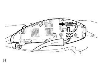
Connect the connector.
-
Attach the clamp.
-
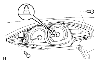
Attach the clip to install the combination meter.
-
Install the 2 screws.
-
-
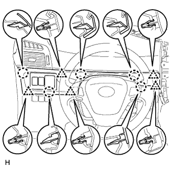
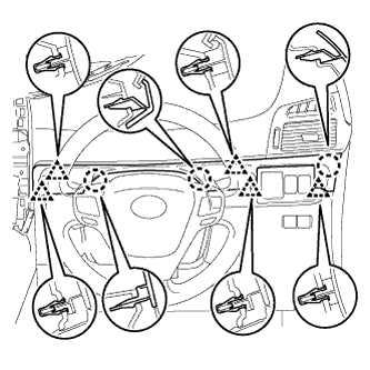
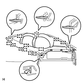
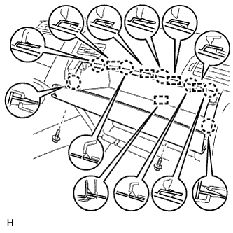
INSTALL INSTRUMENT CLUSTER FINISH PANEL ASSEMBLY
-
Attach the 11 guides and 4 claws to install the instrument cluster finish panel.
-
-
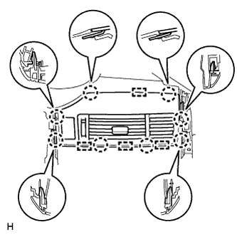
INSTALL CENTER INSTRUMENT PANEL REGISTER ASSEMBLY
-
Connect the connector.
-
Attach the 8 claws and 4 guides to install the center instrument panel register.
-
-
INSTALL INSTRUMENT PANEL FINISH PANEL END RH
-
for Automatic Air Conditioning System:
Attach the 3 clips, claw and 2 guides to install the instrument panel finish panel end RH.
-
for Manual Air Conditioning System:
Attach the 3 clips, claw and guide to install the instrument panel finish panel end RH.
-
-
INSTALL INSTRUMENT PANEL FINISH PANEL END LH
-
for Automatic Air Conditioning System:
Attach the 3 clips and 2 guides to install the instrument panel finish panel end LH.
-
for Manual Air Conditioning System:
Attach the 3 clips and guide to install the instrument panel finish panel end LH.
-
-
INSTALL GLOVE COMPARTMENT DOOR SUB-ASSEMBLY
-
Connect the connector.
-
Attach the 7 claws and 5 guides to install the glove compartment door.
-
Install the 2 screws.
-
-
INSTALL FRONT PILLAR GARNISH LH
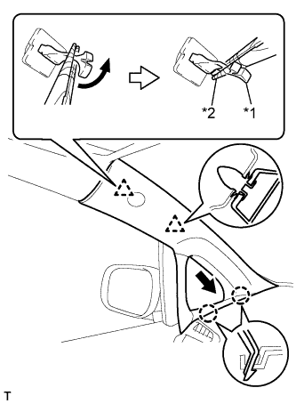
Text in Illustration *1 Front Pillar Garnish Clip *2 Protective Tape
-
Remove the protective cover.
-
Attach the 2 claws.
-
Turn the end of the front pillar garnish clip 90° with needle-nose pliers and install it to the front pillar garnish.
Tech Tips
Tape the tips of the needle-nose pliers before use.
-
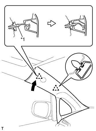
*1 Front Pillar Garnish Clip Attach the 2 clips to install the front pillar garnish.
-
-
INSTALL FRONT PILLAR GARNISH RH
Tech Tips
Use the same procedure described for the LH side.
-
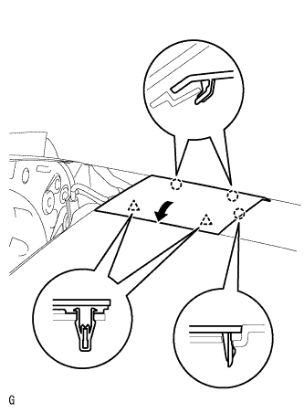
INSTALL FRONT DOOR OPENING TRIM WEATHERSTRIP LH
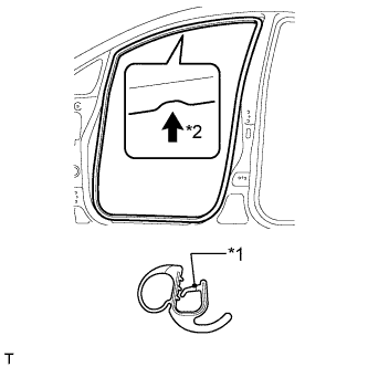
Text in Illustration *1 Paint Mark *2 Mark Position
-
Align the paint mark on the front door opening trim weatherstrip with the mark position on the vehicle and install the weatherstrip as shown in the illustration.
-
-
INSTALL FRONT DOOR OPENING TRIM WEATHERSTRIP RH
Tech Tips
Use the same procedure described for the LH side.
-
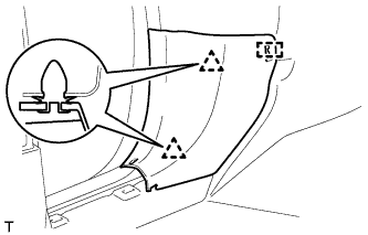
INSTALL COWL SIDE TRIM BOARD LH
-
Attach the 2 clips and guide to install the cowl side trim board.
-
-
INSTALL COWL SIDE TRIM BOARD RH
Tech Tips
Use the same procedure described for the LH side.
-
INSTALL FRONT DOOR SCUFF PLATE LH
-
Attach the 8 claws and 2 clips to install the front door scuff plate.
-
-
INSTALL FRONT DOOR SCUFF PLATE RH
Tech Tips
Use the same procedure described for the LH side.
-
CONNECT CABLE TO NEGATIVE BATTERY TERMINAL
Note
When disconnecting the cable, some systems need to be initialized after the cable is reconnected Click here.
-
CHECK SRS WARNING LIGHT
-
Check the SRS warning light Click here.
-