UPPER INSTRUMENT PANEL REMOVAL

Tech Tips
-
Use the same procedure for RHD and LHD vehicles.
-
The procedure listed below is for LHD vehicles.
-
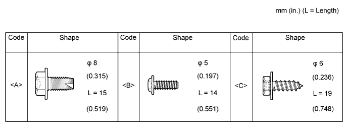
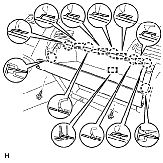
TABLE OF BOLT, SCREW AND NUT
Tech Tips
All bolts, screws and nuts relevant to installing and removing the instrument panel are shown along with their alphabet code in the table below.
-
PRECAUTION
Note
After turning the ignition switch off, waiting time may be required before disconnecting the cable from the battery terminal. Therefore, make sure to read the disconnecting the cable from the battery terminal notice before proceeding with work Click here.
-
DISCONNECT CABLE FROM NEGATIVE BATTERY TERMINAL
CAUTION:
Wait at least 90 seconds after disconnecting the cable from the negative (-) battery terminal to disable the SRS system.
Note
When disconnecting the cable some systems need to be initialized after the cable is reconnected Click here.
-
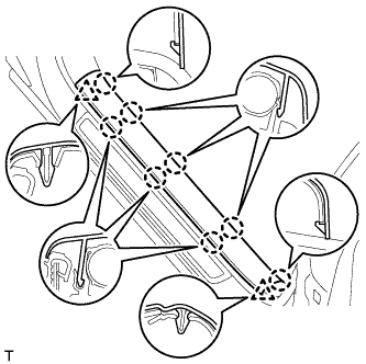
REMOVE FRONT DOOR SCUFF PLATE LH
-
Detach the 8 claws and 2 clips, and remove the front door scuff plate.
-
-
REMOVE FRONT DOOR SCUFF PLATE RH
Tech Tips
Use the same procedure described for the LH side.
-
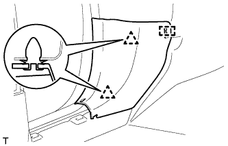
REMOVE COWL SIDE TRIM BOARD LH
-
Detach the 2 clips and guide, and remove the cowl side trim board.
-
-
REMOVE COWL SIDE TRIM BOARD RH
Tech Tips
Use the same procedure described for the LH side.
-
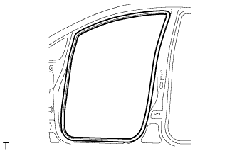
REMOVE FRONT DOOR OPENING TRIM WEATHERSTRIP LH
-
Remove the front door opening trim weatherstrip.
-
-
REMOVE FRONT DOOR OPENING TRIM WEATHERSTRIP RH
Tech Tips
Use the same procedure described for the LH side.
-
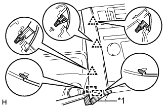
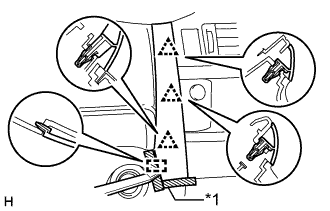
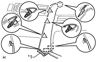
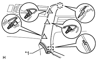
REMOVE FRONT PILLAR GARNISH LH
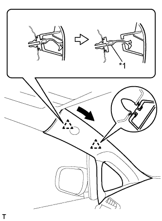
Text in Illustration *1 Front Pillar Garnish Clip
-
Pull the upper part of the garnish toward the inside of the cabin and detach the 2 clips.
Tech Tips
Allow the front pillar garnish to hang by the front pillar garnish clip.
-
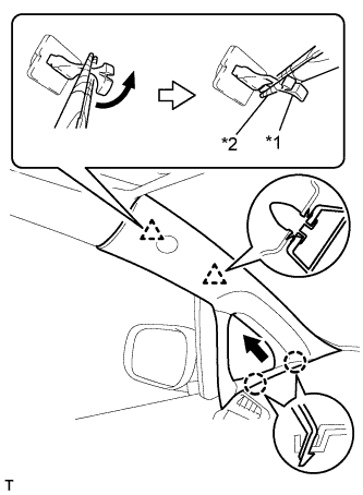
Text in Illustration *1 Front Pillar Garnish Clip *2 Protective Tape Turn the end of the front pillar garnish clip 90° with needle-nose pliers and remove it from the front pillar garnish.
Note
-
Front pillar garnish clips are reusable if they are not removed from the vehicle and have no damage.
-
Replace the front pillar garnish clips with new ones if they are removed from the vehicle.
Tech Tips
Tape the tips of the needle-nose pliers before use.
-
-
Detach the 2 claws and remove the front pillar garnish.
-
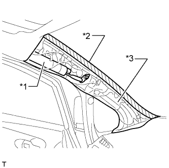
Text in Illustration *1 Curtain Shield Airbag Assembly *2 Adhesive Tape *3 Protective Cover w/ Curtain Shield Airbag:
Protect the curtain shield airbag assembly.
-
Completely cover the airbag with a cloth or nylon sheet and secure the ends of the cover with adhesive tape as shown in the illustration.
Note
Cover the curtain shield airbag with a protective cover as soon as the front pillar garnish is removed.
-
-
-
REMOVE FRONT PILLAR GARNISH RH
Tech Tips
Use the same procedure described for the LH side.
-
REMOVE GLOVE COMPARTMENT DOOR SUB-ASSEMBLY
-
Remove the 2 screws <B>.
-
Detach the 7 claws and 5 guides.
-
Disconnect the connector and remove the glove compartment door.
-
-
REMOVE INSTRUMENT PANEL FINISH PANEL END LH
-
for Automatic Air Conditioning System:
-
Text in Illustration *1 Protective Tape Put protective tape around the instrument panel finish panel end LH.
-
Using a moulding remover A, detach the 3 clips and 2 guides, and remove the instrument panel finish panel end LH.
-
-
for Manual Air Conditioning System:
-
Text in Illustration *1 Protective Tape Put protective tape around the instrument panel finish panel end LH.
-
Using a moulding remover A, detach the 3 clips and guide, and remove the instrument panel finish panel end LH.
-
-
-
REMOVE INSTRUMENT PANEL FINISH PANEL END RH
Text in Illustration *1 Protective Tape
-
for Automatic Air Conditioning System:
-
Put protective tape around the instrument panel finish panel end RH.
-
Using a moulding remover A, detach the 3 clips, claw and 2 guides, and remove the instrument panel finish panel end RH.
-
-
Text in Illustration *1 Protective Tape for Manual Air Conditioning System:
-
Put protective tape around the instrument panel finish panel end RH.
-
Using a moulding remover A, detach the 3 clips, claw and guide, and remove the instrument panel finish panel end.
-
-
-
REMOVE CENTER INSTRUMENT PANEL REGISTER ASSEMBLY
-
Detach the 8 claws and 4 guides.
-
Disconnect the connector and remove the center instrument panel register.
-
-
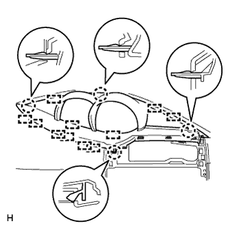
REMOVE INSTRUMENT CLUSTER FINISH PANEL ASSEMBLY
-
Detach the 4 claws and 11 guides, and remove the instrument cluster finish panel.
-
-
REMOVE COMBINATION METER ASSEMBLY
-
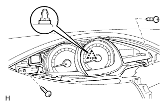
Remove the 2 screws.
-
Detach the clip.
-
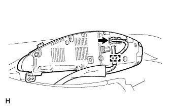
Detach the clamp.
-
Disconnect the connector and remove the combination meter.
-
-
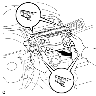
REMOVE CENTER INSTRUMENT CLUSTER FINISH PANEL SUB-ASSEMBLY (w/o Audio, for Radio and Display Type)
-
Detach the 4 clips, 3 claws and 3 guides, and remove the center instrument cluster finish panel.
-
-
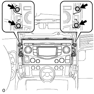
REMOVE STEREO OPENING COVER WITH BRACKET (w/o Audio)
-
Remove the 4 bolts and stereo opening cover.
-
-
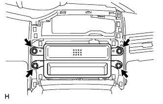
REMOVE RADIO RECEIVER ASSEMBLY (for Radio Receiver Type)
-
Remove the 4 screws.
-
Pull the radio receiver assembly with bracket to detach the 4 clips on the backside of the radio receiver assembly with bracket.
-
Disconnect the connectors and remove the radio receiver assembly with bracket.
-
-
REMOVE RADIO AND DISPLAY RECEIVER ASSEMBLY (for Radio and Display Type)
-
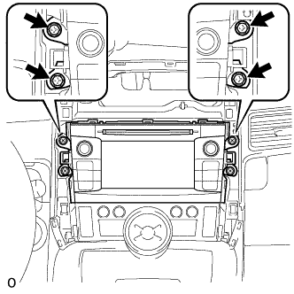
Remove the 4 screws.
-
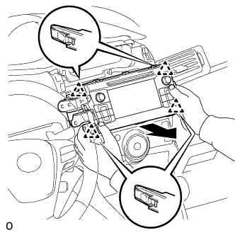
Pull the radio receiver and display receiver assembly with bracket to detach the 4 clips on the backside of the radio and display receiver assembly with bracket.
-
Disconnect the connectors and remove the radio and display receiver assembly with bracket.
-
-
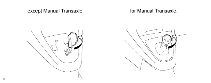
REMOVE SHIFT LEVER KNOB SUB-ASSEMBLY
-
Twist the shift lever knob in the direction indicated by the arrow and remove it.
-
-
REMOVE POSITION INDICATOR HOUSING ASSEMBLY (except Manual Transaxle)
-
Detach the 5 claws and 3 clips.
-
Disconnect the connector and remove the position indicator housing.
-
-
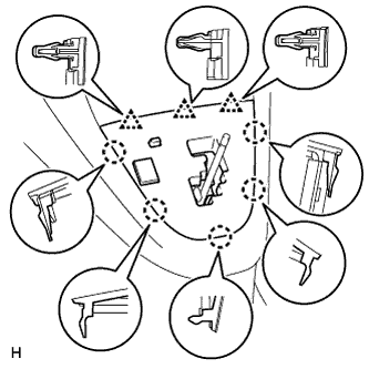
REMOVE SHIFTING HOLE COVER (for Manual Transaxle)
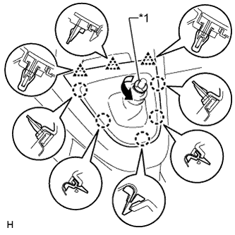
Text in Illustration *1 T Washer
-
Twist the T washer in the direction indicated by the arrow and remove it.
-
Remove the knob spring.
-
Detach the 5 claws and 3 clips, and remove the shifting hole cover.
-
-
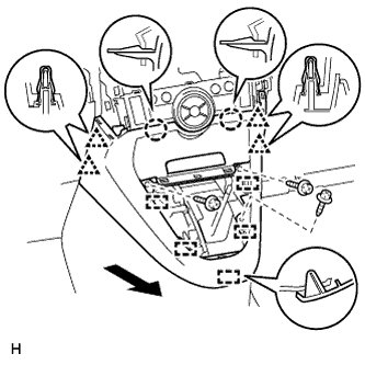
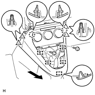
REMOVE LOWER CENTER INSTRUMENT PANEL FINISH PANEL (except Manual Transaxle)
-
for Automatic Air Conditioning System:
-
Remove the 3 screws <C>.
-
Detach the 2 claws, 4 clips and 5 guides, and remove the lower center instrument panel finish panel.
Tech Tips
If the 2 claws shown in the illustration are difficult to detach, detach the 4 clips of the air conditioning control and remove the lower center instrument panel finish panel together with the air conditioning control.
-
-
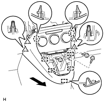
for Manual Air Conditioning System:
-
Remove the 3 screws <C>.
-
Detach the 4 clips, 2 claws and 5 guides, and remove the lower center instrument panel finish panel.
-
-
-
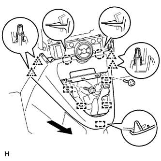
REMOVE LOWER CENTER INSTRUMENT PANEL FINISH PANEL (for Manual Transaxle)
-
for Automatic Air Conditioning System:
-
Remove the 2 screws <C>.
-
Detach the 2 claws, 4 clips and 5 guides, and remove the lower center instrument panel finish panel.
Tech Tips
If the 2 claws shown in the illustration are difficult to detach, detach the 4 clips of the air conditioning control and remove the lower center instrument panel finish panel together with the air conditioning control.
-
-
for Manual Air Conditioning System:
-
Remove the 2 screws <C>.
-
Detach the 4 clips, 2 claws and 5 guides, and remove the lower center instrument panel finish panel.
-
-
-
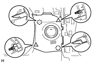
REMOVE NO. 2 SWITCH HOLE BASE
-
for LHD:
Detach the 5 claws and 5 clips, and remove the No. 2 switch hole base.
-
for RHD:
Detach the 3 claws and 5 clips, and remove the No. 2 switch hole base.
-
-
REMOVE NO. 1 SWITCH HOLE BASE
-
w/ Entry and Start System:
-
Detach the 2 claws and 2 clips.
-
Disconnect the connector and remove the No. 1 switch hole base.
-
-
w/o Entry and Start System:
-
Detach the 2 claws and 2 clips, and remove the No. 1 switch hole base.
-
-
-
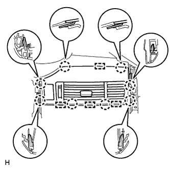
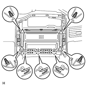
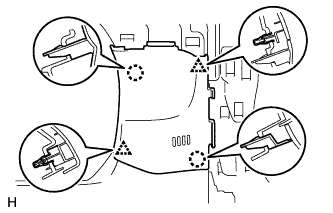
REMOVE NO. 1 INSTRUMENT PANEL SPEAKER PANEL SUB-ASSEMBLY
-
for 4 Speakers:
-
Detach the claws and clips shown in the illustration on the bottom of the panel. Then, using the 2 claws on the side of the panel towards the front of the vehicle as pivot points, lift up the panel in the direction indicated by the arrow in the illustration to remove the No. 1 instrument panel speaker panel.
-
-
for 6 Speakers:
-
Detach the claws and clips shown in the illustration on the bottom of the panel. Then, using the 2 claws on the side of the panel towards the front of the vehicle as pivot points, lift up the panel in the direction indicated by the arrow in the illustration until the speaker connector can be disconnected.
-
Disconnect the connector and remove the No. 1 instrument panel speaker panel together with the speaker.
-
-
-
REMOVE NO. 2 INSTRUMENT PANEL SPEAKER PANEL SUB-ASSEMBLY
Tech Tips
Use the same procedure described for the No. 1 instrument panel speaker panel.
-
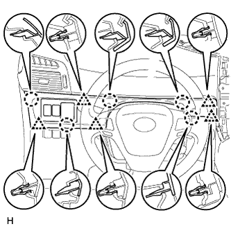
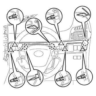
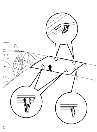
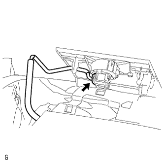
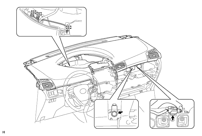
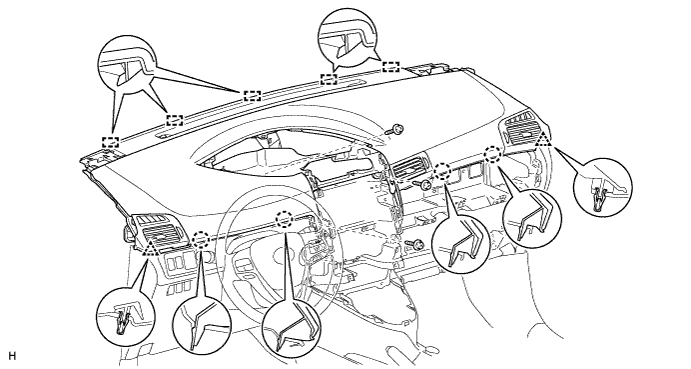
REMOVE INSTRUMENT PANEL SAFETY PAD SUB-ASSEMBLY
-
Remove the passenger airbag bolt <A>.
-
Disconnect the connector and clamps.
-
Remove the 3 screws <B>.
-
Pull up the instrument panel safety pad to detach the 2 clips, 4 claws and 5 guides, and remove the instrument panel safety pad.
Note
Be careful not to damage the steering wheel.
-