ROOF SUNSHADE SYSTEM Roof Sunshade does not Move by Operating Roof Sunshade Switch
DESCRIPTION
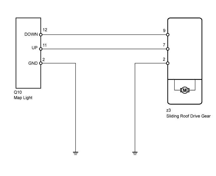
The sliding roof drive gear receives roof sunshade switch signals and drives its built-in motor.
WIRING DIAGRAM
INSPECTION PROCEDURE
PROCEDURE
-
PERFORM ACTIVE TEST USING INTELLIGENT TESTER (ROOF SUNSHADE OPERATION)
-
Select the Active Test, use the intelligent tester to generate a control command, and then check that the roof sunshade slides open/closed Click here.
Sliding Roof Tester Display Test Part Control Range Diagnostic Note Slide Roof Operate roof sunshade Clos/Up: Roof sunshade close operation occurs
Opn/Dwn: Roof sunshade open operation occurs
OFF: Roof sunshade is not operating
Be careful to avoid injuries as this test causes vehicle parts to move. OK Roof sunshade operates normally.
NG 
REPLACE SLIDING ROOF DRIVE GEAR SUB-ASSEMBLY Click here
OK 
-
-
READ VALUE USING INTELLIGENT TESTER (ROOF SUNSHADE SWITCH)
-
Use the Data List to check if the roof sunshade switch is functioning properly Click here.
Sliding Roof Item Measurement Item/Range Normal Condition Diagnostic Note Open Switch Roof sunshade switch open signal / ON or OFF ON: Open switch pressed
OFF: Open switch not pressed
- Close Switch Roof sunshade switch close signal / ON or OFF ON: Close switch pressed
OFF: Close switch not pressed
- OK When the switch is operated, the intelligent tester display changes as shown in the table.
NG 
INSPECT MAP LIGHT ASSEMBLY (ROOF SUNSHADE SWITCH) Click here
OK 
REPLACE SLIDING ROOF DRIVE GEAR SUB-ASSEMBLY Click here
-
-
INSPECT MAP LIGHT ASSEMBLY (ROOF SUNSHADE SWITCH)
-
Remove the map light Click here.
-
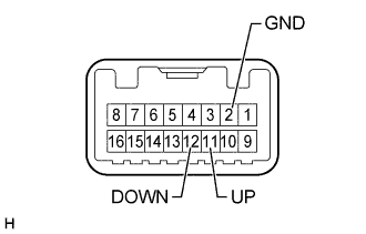
Measure the resistance according to the value(s) in the table below.
Standard Resistance Tester Connection Switch Condition Specified Condition 11 (UP) - 2 (GND) Open switch is pressed Below 1 Ω 11 (UP) - 2 (GND) Open switch is not pressed 10 kΩ or higher 12 (DOWN) - 2 (GND) Close switch is pressed Below 1 Ω 12 (DOWN) - 2 (GND) Close switch is not pressed 10 kΩ or higher
NG
REPLACE MAP LIGHT ASSEMBLY Click here
OK
-
-
CHECK HARNESS AND CONNECTOR (SLIDING ROOF DRIVE GEAR SUB-ASSEMBLY - MAP LIGHT ASSEMBLY)
-
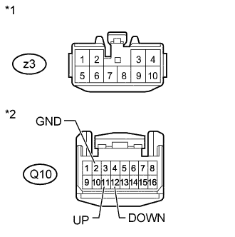
Text in Illustration *1 Front view of wire harness connector
(to Sliding Roof Drive Gear)
*2 Front view of wire harness connector
(to Map Light)
Disconnect the z3 sliding roof drive gear connector.
-
Disconnect the Q10 map light connector.
-
Measure the resistance according to the value(s) in the table below.
Standard Resistance Tester Connection Condition Specified Condition z3-7 - Q10-11 (UP) Always Below 1 Ω z3-9 - Q10-12 (DOWN) Always Below 1 Ω Q10-2 (GND) - Body ground Always Below 1 Ω z3-2 - Body ground Always Below 1 Ω z3-7 or Q10-11 (UP) - Body ground Always 10 kΩ or higher z3-9 or Q10-12 (DOWN) - Body ground Always 10 kΩ or higher
NG
REPAIR OR REPLACE HARNESS OR CONNECTOR
OK
REPLACE SLIDING ROOF DRIVE GEAR SUB-ASSEMBLY Click here
-