HEATER EXHAUST PIPE (w/ Combustion Type Power Heater) INSTALLATION

-
INSTALL HEAT EXCHANGER UNIT GASKET
-
Install 2 new heat exchanger unit gaskets.
-
-
INSTALL NO. 2 EXHAUST PIPE SUB-ASSEMBLY
-
Install the No. 2 exhaust pipe sub-assembly with the 2 bolts.
- Torque:
- 5.4 N*m { 55 kgf*cm, 48 in.*lbf }
-
-
INSTALL HEATER WITH EXHAUST PIPE ASSEMBLY
-
Install the heater with exhaust pipe assembly with the 3 nuts.
- Torque:
- 7.5 N*m { 77 kgf*cm, 66 in.*lbf }
-
Attach the clamp.
-
Connect the 3 hoses.
-
Using pliers, grip the claws of the clips and slide the 3 clips.
-
Connect the connector.
-
-
INSTALL NO. 1 EXHAUST PIPE SUB-ASSEMBLY
-
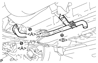
Install the No. 1 exhaust pipe sub-assembly with the 2 nuts labeled <A>.
- Torque:
- 7.5 N*m { 77 kgf*cm, 66 in.*lbf }
-
Install the nut labeled <B>.
- Torque:
- 7.5 N*m { 77 kgf*cm, 66 in.*lbf }
-
-
INSTALL AIR DUCT
-
Install the air duct with the clip.
-
-
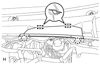
INSTALL OUTER COWL TOP PANEL
-
Install the cowl top panel with the 9 bolts.
- Torque:
- 12 N*m { 122 kgf*cm, 9 ft.*lbf }
-
-
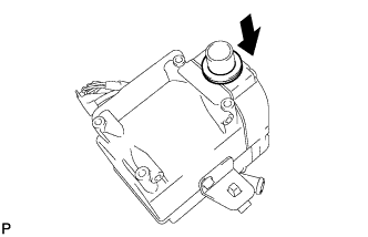
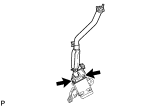
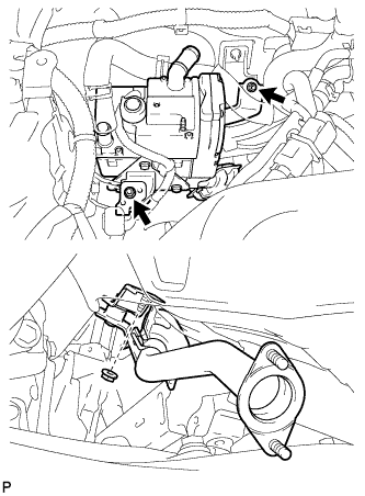
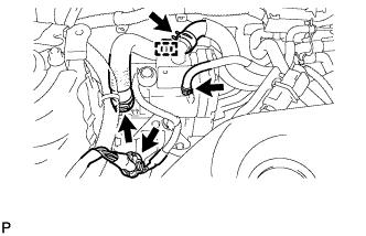
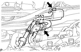
INSTALL DIFFERENTIAL PRESSURE SENSOR ASSEMBLY (for DPF)
-
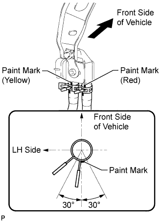
Connect the 2 vacuum hoses.
Note
Connect the vacuum hoses so that the painted marks of the 2 vacuum hoses are as shown in the illustration.
-
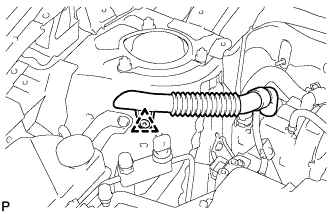
Install the sensor with the bolt.
- Torque:
- 8.0 N*m { 82 kgf*cm, 71 in.*lbf }
-
Connect the sensor connector and attach the wire harness clamp.
-
-
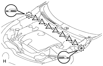
INSTALL WINDSHIELD WIPER MOTOR AND LINK ASSEMBLY
-
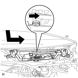
Move the wiper motor and link in the direction shown by the arrow in the illustration to attach the wiper cushion to the body and install the wiper motor and link.
-
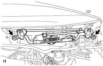
Install the 2 bolts.
- Torque:
- 5.5 N*m { 56 kgf*cm, 49 in.*lbf }
-
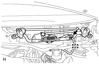
Connect the connector and attach the clamp to install the wire harness to the cowl top panel.
-
-
INSTALL COWL TOP VENTILATOR LOUVER LH
-
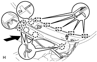
Attach the 6 claws and 5 guides to install the cowl top ventilator louver LH.
-
Install the clip.
-
Attach the 2 claws and 2 guides to install the center cowl top ventilator louver.
-
-
INSTALL COWL TOP VENTILATOR LOUVER RH
-
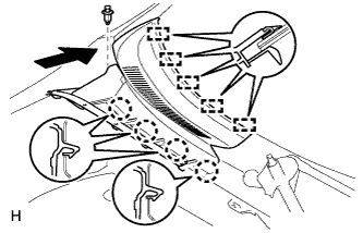
Attach the 4 claws and 5 guides to install the cowl top ventilator louver RH.
-
Install the clip.
-
-
INSTALL HOOD TO COWL TOP SEAL
-
Attach the 7 clips and 2 claws to install the hood to cowl top seal.
-
-
INSTALL FRONT WIPER ARM AND BLADE ASSEMBLY LH
-
Operate the wiper and stop the front wiper motor and link at the automatic stop position.
-
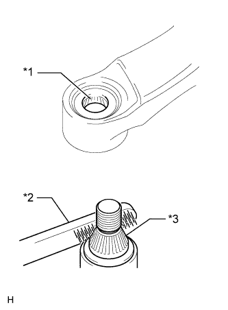
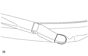
Text in Illustration *1 Wiper Arm Serrations *2 Wire Brush *3 Wiper Pivot Serrations Clean the wiper arm serrations.
-
When reusing the front wiper motor and link assembly:
-
Clean the wiper pivot serrations with a wire brush.
-
-
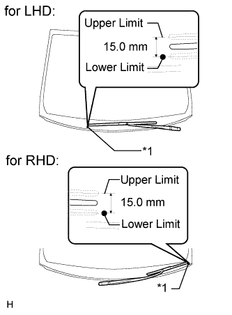
Text in Illustration *1 Mark for Blade Position Position the blade tip within the range shown in the illustration.
Tech Tips
The lower limit of the range is indicated by the mark on the glass.
-
Install the front wiper arm and blade assembly LH with the nut.
- Torque:
- 26 N*m { 265 kgf*cm, 19 ft.*lbf }
Tech Tips
Hold the arm hinge by hand when tightening the nut.
-
Operate the front wipers while spraying washer fluid on the windshield glass. Make sure that the front wipers function properly and the wipers do not come into contact with the vehicle body.
-
-
INSTALL FRONT WIPER ARM AND BLADE ASSEMBLY RH
-
Operate the wiper and stop the front wiper motor and link at the automatic stop position.
-
Text in Illustration *1 Wiper Arm Serrations *2 Wire Brush *3 Wiper Pivot Serrations Clean the wiper arm serrations.
-
When reusing the front wiper motor and link assembly:
-
Clean the wiper pivot serrations with a wire brush.
-
-
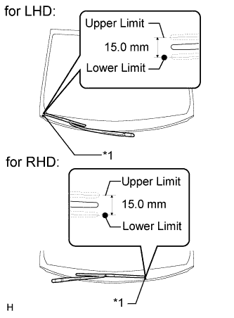
Text in Illustration *1 Mark for Blade Position Position the blade tip within the range shown in the illustration.
Tech Tips
The lower limit of the range is indicated by the mark on the glass.
-
Install the front wiper arm and blade assembly RH with the nut.
- Torque:
- 26 N*m { 265 kgf*cm, 19 ft.*lbf }
Tech Tips
Hold the arm hinge by hand when tightening the nut.
-
-
INSTALL FRONT WIPER ARM HEAD CAP
-
Install the front wiper arm head cap.
Tech Tips
Use the same procedure for all front wiper arm head caps.
-
-
INSTALL NO. 1 ENGINE COVER (for AD Series Engine)
-
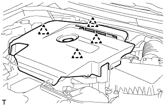
Attach the 4 clips to install the No. 1 engine cover.
-
-
INSTALL NO. 1 ENGINE COVER (for 1WW)
-
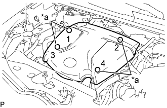
Text in Illustration *a Installation Points Attach the 4 clips to install the No. 1 engine cover.
Tech Tips
When attaching the clips, press the protrusions on the top of the No. 1 engine cover at the clip installation points.
-