CONDENSER (for ZR Series Engine) INSTALLATION

-
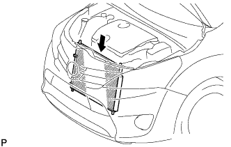
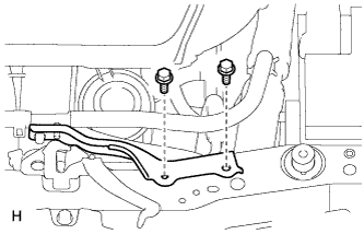
INSTALL CONDENSER ASSEMBLY WITH RECEIVER
-
Install the condenser assembly with receiver as shown in the illustration.
Tech Tips
If the condenser is replaced with a new one, add compressor oil to the new condenser.
Capacity 40 cc (1.4 fl.oz) Compressor oil ND-OIL 8 or equivalent
-
-
CONNECT SUCTION PIPE SUB-ASSEMBLY
-
Remove the attached vinyl tape from the pipe and connecting part of the cooler condenser assembly.
-
Sufficiently apply compressor oil to a new O-ring and the fitting surface of the pipe joint.
Compressor oil ND-OIL 8 or equivalent -
Install the O-ring to the suction pipe sub-assembly.
-
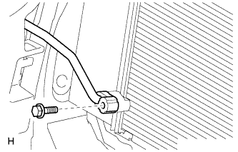
Connect the suction pipe sub-assembly to the cooler condenser assembly with the bolt.
- Torque:
- 5.4 N*m { 55 kgf*cm, 48 in.*lbf }
-
-
CONNECT DISCHARGE HOSE SUB-ASSEMBLY
-
Remove the attached vinyl tape from the hose and connecting part of the cooler condenser assembly.
-
Sufficiently apply compressor oil to a new O-ring and the fitting surface of the hose joint.
Compressor oil ND-OIL 8 or equivalent -
Install the O-ring to the discharge hose sub-assembly.
-
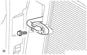
Connect the discharge hose sub-assembly to the cooler condenser assembly with the bolt.
- Torque:
- 5.4 N*m { 55 kgf*cm, 48 in.*lbf }
-
-
INSTALL NO. 2 FAN SHROUD
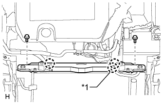
Text in Illustration *1 except Manual Transaxle
-
Attach the 2 claws to install the fan shroud.
-
Install the 2 bolts.
- Torque:
- 7.0 N*m { 71 kgf*cm, 62 in.*lbf }
-
except Manual Transaxle:
Attach the clamp to connect the No. 1 water by-pass hose.
-
-
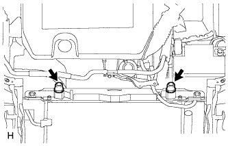
INSTALL RADIATOR SUPPORT CUSHION
-
Install the 2 cushions.
-
-
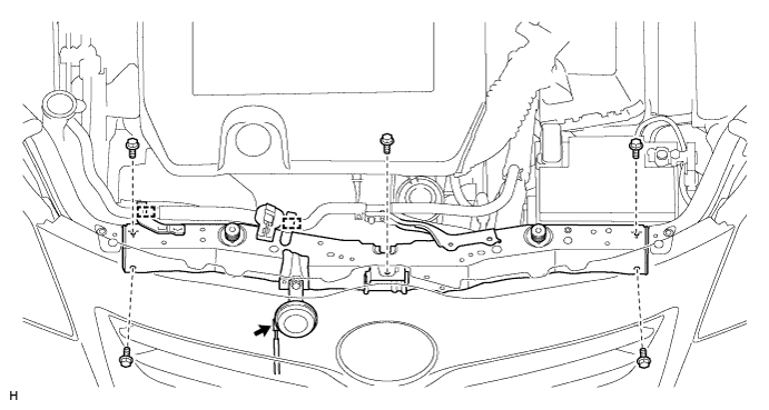
INSTALL UPPER RADIATOR SUPPORT
-
Install the upper radiator support with the 5 bolts.
- Torque:
- 13 N*m { 133 kgf*cm, 9 ft.*lbf }
-
Attach the 2 clamps to connect the No. 1 water by-pass hose.
-
Connect the horn connector.
-
-
INSTALL HOOD LOCK ASSEMBLY
-
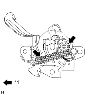
Text in Illustration *1 MP grease Apply MP grease to the sliding areas of the lock.
-
for LHD:
-
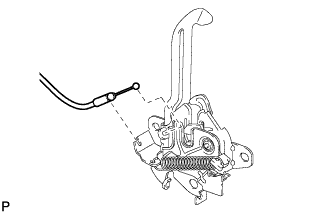
Connect the hood lock control cable.
-
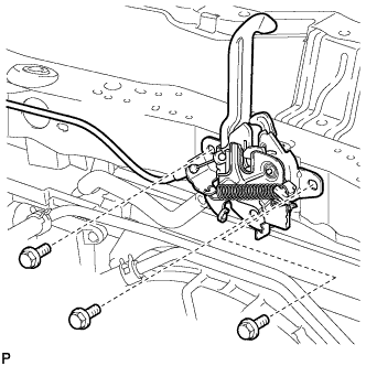
Install the hood lock with the 3 bolts.
- Torque:
- 7.5 N*m { 76 kgf*cm, 66 in.*lbf }
-
-
for RHD:
-
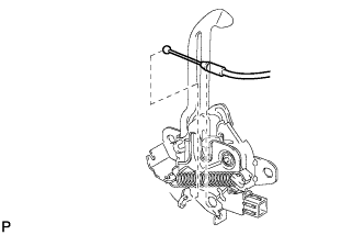
Connect the hood lock control cable.
-
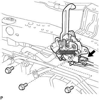
Connect the connector.
-
Install the hood lock with the 3 bolts.
- Torque:
- 7.5 N*m { 76 kgf*cm, 66 in.*lbf }
-
-
-
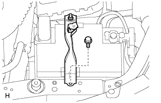
INSTALL BATTERY CLAMP SUB-ASSEMBLY
-
Install the battery clamp with the bolt.
-
-
INSTALL NO. 1 WATER HOSE CLAMP BRACKET
-
Install the hose clamp bracket with the 2 bolts.
- Torque:
- 5.0 N*m { 51 kgf*cm, 44 in.*lbf }
-
-
CHARGE REFRIGERANT
- SST
- 09985-20010 ( 09985-02130, 09985-02150, 09985-02090, 09985-02110, 09985-02010, 09985-02050, 09985-02060, 09985-02070 )
-
Perform vacuum purging using a vacuum pump.
-
Charge refrigerant HFC-134a (R134a).
Standard 440 +/-30 g (15.5 +/-1.1 oz) 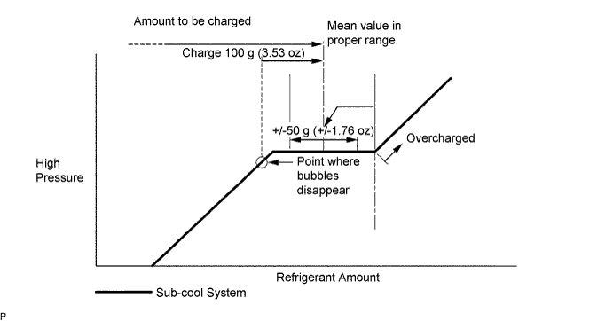
Note
-
Do not operate the cooler compressor before charging refrigerant as the cooler compressor will not work properly without any refrigerant, and will overheat.
-
Approximately 100 g (3.53 oz) of refrigerant may need to be charged after bubbles disappear. The refrigerant amount should be checked by measuring its quantity, and not with the sight glass.
-
-
INSPECT HOOD SUB-ASSEMBLY
-
Check that the clearance measurements of areas A to F are within the standard range.
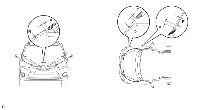
Standard Area Specified Condition Area Specified Condition A 2.35 to 6.35 mm (0.0925 to 0.250 in.) B -1.15 to 2.85 mm (-0.0453 to 0.112 in.) C (Reference) 2.75 to 6.75 mm (0.108 to 0.266 in.) D (Reference) -1.75 to 2.25 mm (-0.0689 to 0.0886 in.) E 1.7 to 4.7 mm (0.0787 to 0.185 in.) F -0.2 to 2.8 mm (-0.0079 to 0.110 in.)
-
-
ADJUST HOOD SUB-ASSEMBLY
-
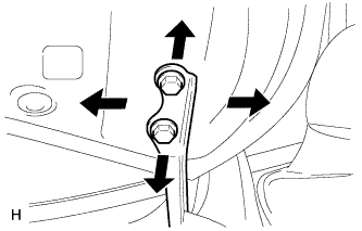
Adjust the hood position.
-
Loosen the 4 hinge bolts on the hood.
-
Move the hood and adjust the clearance between the hood and front fender.
-
Tighten the 4 hinge bolts on the hood after the adjustment.
- Torque:
- 13 N*m { 133 kgf*cm, 10 ft.*lbf }
-
-
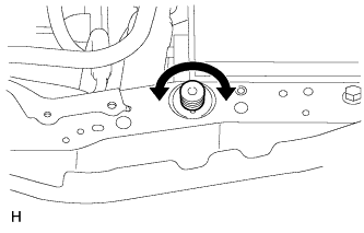
Adjust the cushion rubber so that the hood and fender are aligned.
Tech Tips
Raise or lower the front end of the hood by turning the cushion rubber.
-
Adjust the hood lock.
-
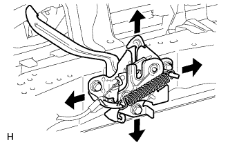
Loosen the 3 bolts.
-
Adjust the hood lock position so that the striker can enter it smoothly.
-
Tighten the 3 bolts after the adjustment.
- Torque:
- 7.5 N*m { 76 kgf*cm, 66 in.*lbf }
-
-
-
INSTALL FRONT BUMPER COVER
-
Install the front bumper cover Click here.
-
-
WARM UP ENGINE
-
Warm up the engine at less than 1850 rpm for 2 minutes or more after charging the refrigerant.
Note
Be sure to warm up the compressor by turning the A/C switch on after removing and installing the cooler refrigerant lines (including the compressor) to prevent damage to the compressor.
-
-
CHECK FOR REFRIGERANT GAS LEAK
-
After recharging the refrigerant gas, check for refrigerant gas leakage using a halogen leak detector.
-
Perform the operation observing the following instructions:
-
Stop the engine.
-
Secure good ventilation (the halogen leak detector may react to volatile gases other than refrigerant, such as evaporated gasoline or exhaust gas).
-
Repeat the test 2 or 3 times.
-
Make sure that some refrigerant remains in the refrigeration system.
Tech Tips
When the compressor is off: approximately 392 to 588 kPa (4.0 to 6.0 kgf/cm2, 57 to 85 psi).
-
-
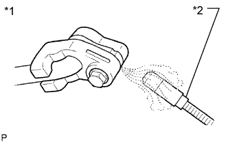
Text in Illustration *1 Check for Leakage *2 Halogen Leak Detector Using a halogen leak detector, check the refrigerant line for leakage.
-
If a gas leak is not detected from the drain hose, remove the blower motor control (blower resistor) from the cooling unit. Insert the halogen leak detector sensor into the unit and check for gas leakage.
-
Disconnect the pressure switch connector and wait for approximately 20 minutes. Bring the halogen leak detector close to the pressure switch and check for gas leakage.
-