COMPRESSOR (for ZR Series Engine) REMOVAL

-
REMOVE NO. 2 CYLINDER HEAD COVER
-
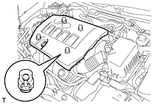
Hold the rear of the cover and raise it to detach the 2 clips on the rear of the cover. Continue to raise the cover to detach the 2 clips on the front of the cover and remove the cover.
Note
Attempting to detach both front and rear clips at the same time may cause the cover to break.
-
-
REMOVE BATTERY SERVICE HOLE COVER
-
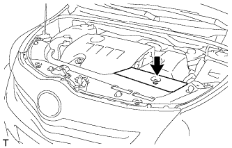
Remove the clip and battery service hole cover.
-
-
REMOVE RADIATOR SUPPORT OPENING COVER
-
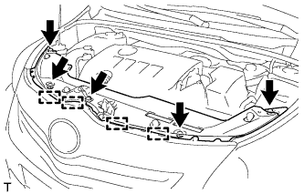
Remove the 5 clips.
-
Detach the 4 hooks and remove the radiator support opening cover.
-
-
RECOVER REFRIGERANT FROM REFRIGERATION SYSTEM
-
Start the engine.
-
Turn the A/C switch on.
-
Operate the cooler compressor while the engine speed is approximately 1000 rpm for 5 to 6 minutes to circulate the refrigerant and collect the compressor oil remaining in each component into the cooler compressor.
-
Stop the engine.
-
Recover the refrigerant from the A/C system using a refrigerant recovery unit.
-
-
REMOVE FRONT LOWER BUMPER ABSORBER
-
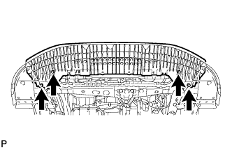
Remove the 4 bolts and front lower bumper absorber.
-
-
REMOVE NO. 1 ENGINE UNDER COVER
-
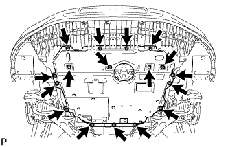
Remove the 11 clips, 6 bolts and under cover.
-
-
REMOVE REAR ENGINE UNDER COVER RH
-
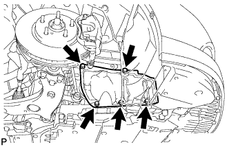
Remove the 5 clips and under cover RH.
-
-
REMOVE FRONT SUSPENSION MEMBER REINFORCEMENT RH
-
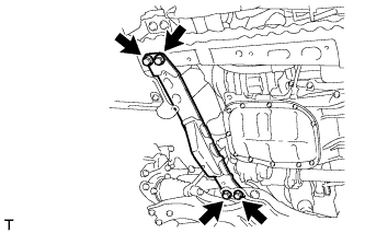
Remove the 4 bolts and front suspension member reinforcement RH.
-
-
REMOVE V-RIBBED BELT
-
for 1ZR-FAE:
Remove the V-ribbed belt Click here.
-
for 2ZR-FAE:
Remove the V-ribbed belt Click here.
-
-
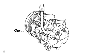
DISCONNECT DISCHARGE HOSE SUB-ASSEMBLY
-
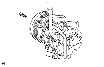
Remove the bolt and disconnect the discharge hose sub-assembly from the compressor assembly with pulley.
Note
Seal the openings of the disconnected parts using vinyl tape to prevent entry of moisture and foreign matter.
-
Remove the O-ring from the discharge hose sub-assembly.
Note
Seal the openings of the disconnected parts using vinyl tape to prevent entry of moisture and foreign matter.
-
-
DISCONNECT SUCTION HOSE SUB-ASSEMBLY
-
Remove the bolt and disconnect the suction hose sub-assembly from the compressor assembly with pulley.
Note
Seal the openings of the disconnected parts using vinyl tape to prevent entry of moisture and foreign matter.
-
Remove the O-ring from the suction hose sub-assembly.
Note
Seal the openings of the disconnected parts using vinyl tape to prevent entry of moisture and foreign matter.
-
-
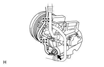
REMOVE COMPRESSOR ASSEMBLY WITH PULLEY
-
Detach the 2 clamps.
-
Disconnect the connector.
-
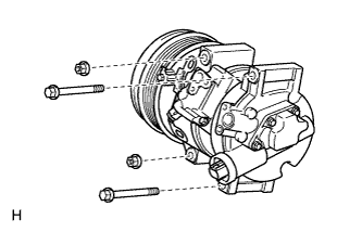
Remove the 2 bolts and 2 nuts.
-
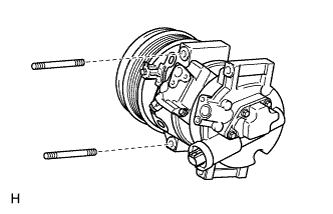
Using a "TORX" socket wrench (E8), remove the 2 stud bolts and compressor assembly with pulley.
-