AIR CONDITIONING UNIT REMOVAL

Tech Tips
-
Use the same procedure for RHD and LHD vehicles.
-
The procedure listed below is for LHD vehicles.
-
PLACE FRONT WHEELS FACING STRAIGHT AHEAD
-
RECOVER REFRIGERANT FROM REFRIGERATION SYSTEM
-
Start the engine.
-
Turn the A/C switch on.
-
Operate the cooler compressor while the engine speed is approximately 1000 rpm for 5 to 6 minutes to circulate the refrigerant and collect the compressor oil remaining in each component into the cooler compressor.
-
Stop the engine.
-
Recover the refrigerant from the A/C system using a refrigerant recovery unit.
-
-
DRAIN ENGINE COOLANT (for 1AD-FTV)
-
Loosen the radiator drain cock plug.
Tech Tips
Collect the coolant in a container and dispose of it according to the regulations in your area.
-
Remove the radiator reservoir cap.
CAUTION:
Do not remove the radiator reservoir cap and air release plug while the engine and radiator are still hot. Pressurized, hot engine coolant and steam may be released and cause serious burns.
-
Loosen the cylinder block drain cock plug. Then drain the coolant from the engine.
Tech Tips
The plug is on the backside of the generator on the EGR cooler side.
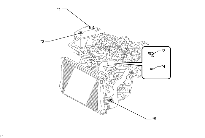
Text in Illustration *1 Radiator Reservoir Cap *2 Air Release Plug *3 Cylinder Block Drain Cock Plug (Type A) *4 Cylinder Block Drain Cock Plug (Type B) *5 Radiator Drain Cock Plug - -
-
-
DRAIN ENGINE COOLANT (for 2AD-FHV)
-
Loosen the radiator drain cock plug.
Tech Tips
Collect the coolant in a container and dispose of it according to the regulations in your area.
-
Remove the radiator reservoir cap.
CAUTION:
Do not remove the radiator reservoir cap and air release plug, while the engine and radiator are still hot. Pressurized, hot engine coolant and steam may be released and cause serious burns.
-
Loosen the cylinder block drain cock plug. Then drain the coolant from the engine.
Tech Tips
The plug is on the backside of the generator on the EGR cooler side.
Text in Illustration *1 Radiator Reservoir Cap *2 Air Release Plug *3 Cylinder Block Drain Cock Plug (Type A) *4 Cylinder Block Drain Cock Plug (Type B) *5 Radiator Drain Cock Plug - -
-
-
DRAIN ENGINE COOLANT (for 1ZR-FAE)
-
Loosen the radiator drain cock plug.
Tech Tips
Collect the coolant in a container and dispose of it according to the regulations in your area.
-
Remove the radiator reservoir cap.
CAUTION:
Do not remove the radiator reservoir cap while the engine and radiator are still hot.
Pressurized, hot engine coolant and steam may be released and cause serious burns.
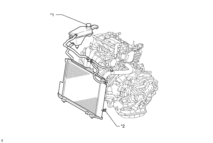
Text in Illustration *1 Radiator Reservoir Cap *2 Radiator Drain Cock Plug
-
-
DRAIN ENGINE COOLANT (for 2ZR-FAE)
-
Loosen the radiator drain cock plug.
Tech Tips
Collect the coolant in a container and dispose of it according to the regulations in your area.
-
Remove the radiator reservoir cap.
CAUTION:
Do not remove the radiator reservoir cap while the engine and radiator are still hot.
Pressurized, hot engine coolant and steam may be released and cause serious burns.
Text in Illustration *1 Radiator Reservoir Cap *2 Radiator Drain Cock Plug
-
-
PRECAUTION
Note
After turning the ignition switch off, waiting time may be required before disconnecting the cable from the battery terminal. Therefore, make sure to read the disconnecting the cable from the battery terminal notice before proceeding with work Click here.
-
DISCONNECT CABLE FROM NEGATIVE BATTERY TERMINAL
CAUTION:
Wait at least 90 seconds after disconnecting the cable from the negative (-) battery terminal to disable the SRS system.
Note
When disconnecting the cable, some systems need to be initialized after the cable is reconnected Click here.
-
REMOVE NO. 1 ENGINE COVER (for AD Series Engine)
-
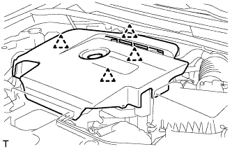
Hold the rear of the cover and slowly raise it to detach the clip on the rear of the cover. Continue to raise the cover to detach the 3 clips on the front and side of the cover and remove the cover.
Note
Attempting to disengage both front and rear clips at the same time may cause the cover to break.
-
-
REMOVE NO. 2 CYLINDER HEAD COVER (for ZR Series Engine)
-
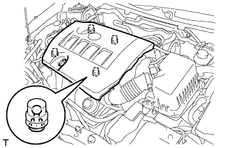
Hold the rear of the cover and raise it to detach the 2 clips on the rear of the cover. Continue to raise the cover to detach the 2 clips on the front of the cover and remove the cover.
Note
Attempting to detach both front and rear clips at the same time may cause the cover to break.
-
-
REMOVE FRONT WIPER ARM HEAD CAP
-
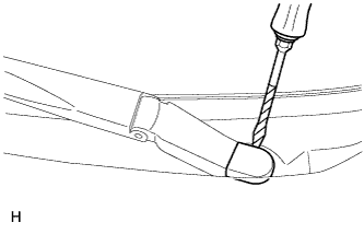
Using a screwdriver, remove the front wiper arm head cap.
Tech Tips
-
Tape the screwdriver tip before use.
-
Use the same procedure for all front wiper arm head caps.
-
-
-
REMOVE FRONT WIPER ARM AND BLADE ASSEMBLY LH
-
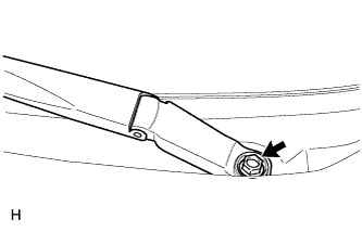
Remove the nut and front wiper arm and blade assembly LH.
-
-
REMOVE FRONT WIPER ARM AND BLADE ASSEMBLY RH
-
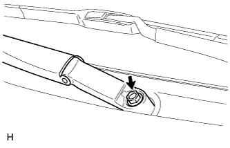
Remove the nut and front wiper arm and blade assembly RH.
-
-
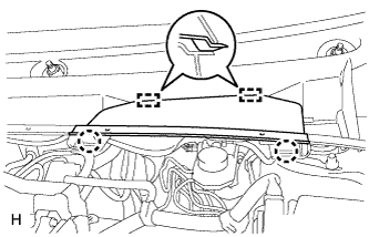
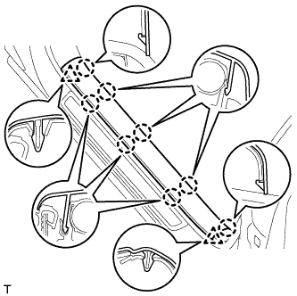
REMOVE HOOD TO COWL TOP SEAL
-
Using a clip remover, detach the 7 clips and 2 claws, and remove the hood to cowl top seal.
-
-
REMOVE COWL TOP VENTILATOR LOUVER LH
-
Detach the 2 claws and 2 guides, and remove the center cowl top ventilator louver.
-
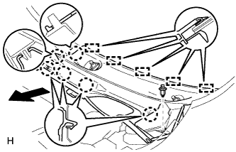
Remove the clip.
-
Detach the 6 claws and 5 guides, and remove the cowl top ventilator louver LH.
-
-
REMOVE COWL TOP VENTILATOR LOUVER RH
-
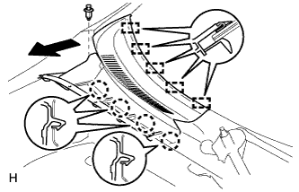
Remove the clip.
-
Detach the 4 claws and 5 guides, and remove the cowl top ventilator louver RH.
-
-
REMOVE WINDSHIELD WIPER MOTOR AND LINK ASSEMBLY
-
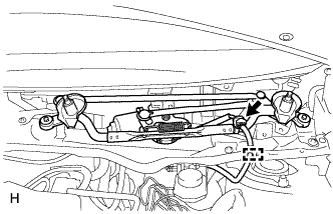
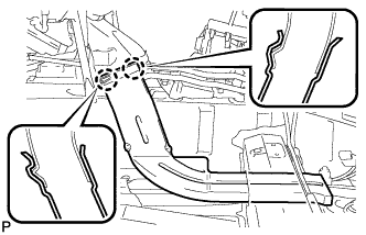
Disconnect the connector. Then detach the clamp and remove the wire harness from the cowl top panel.
-
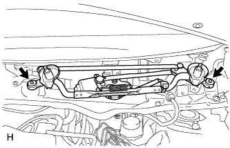
Remove the 2 bolts.
-
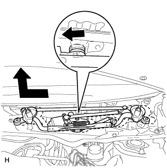
Move the wiper cushion in the direction shown by the arrow in the illustration to detach the wiper cushion from the body and remove the wiper motor and link.
-
-
REMOVE DIFFERENTIAL PRESSURE SENSOR ASSEMBLY (for DPF)
-
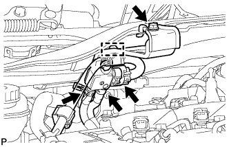
Detach the wire harness clamp and disconnect the sensor connector.
-
Remove the bolt and sensor.
-
Disconnect the 2 vacuum hoses.
-
-
REMOVE COWL TOP OUTER PANEL
-
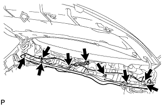
Remove the 9 bolts and outer cowl top panel.
-
-
DISCONNECT SUCTION PIPE SUB-ASSEMBLY
-
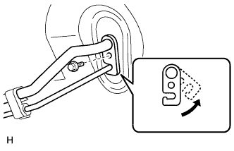
Remove the bolt and slide the hook connector.
-
Disconnect the suction pipe sub-assembly.
-
Remove the O-ring from the suction pipe sub-assembly.
Note
Seal the openings of the disconnected parts using vinyl tape to prevent entry of moisture and foreign matter.
-
-
DISCONNECT AIR CONDITIONING TUBE AND ACCESSORY ASSEMBLY
-
Disconnect the air conditioning tube and accessory assembly.
-
Remove the O-ring from the air conditioning tube and accessory assembly.
Note
Seal the openings of the disconnected parts using vinyl tape to prevent entry of moisture and foreign matter.
-
-
DISCONNECT HEATER OUTLET WATER HOSE
-
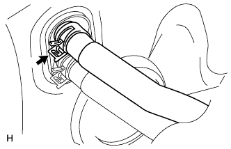
Using pliers, grip the claws of the clip, slide the clip and disconnect the heater outlet water hose.
Note
-
Do not apply excessive force to the heater outlet water hose.
-
Prepare a drain pan or cloth in case the coolant leaks.
-
-
-
DISCONNECT HEATER INLET WATER HOSE
-
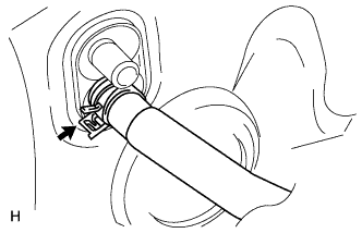
Using pliers, grip the claws of the clip, slide the clip and disconnect the heater inlet water hose.
Note
-
Do not apply excessive force to the heater inlet water hose.
-
Prepare a drain pan or cloth in case the coolant leaks.
-
-
-
REMOVE INSTRUMENT PANEL SAFETY PAD SUB-ASSEMBLY
-
Remove the instrument panel safety pad sub-assembly Click here.
-
-
REMOVE STEERING COLUMN ASSEMBLY
-
Remove the steering column assembly Click here.
-
-
REMOVE FRONT DOOR SCUFF PLATE LH
-
Detach the 8 claws and 2 clips, and remove the front door scuff plate.
-
-
REMOVE COWL SIDE TRIM BOARD LH
-
Detach the 2 clips and guide, and remove the cowl side trim board.
-
-
REMOVE FRONT DOOR SCUFF PLATE RH
Tech Tips
Use the same procedure described for the LH side.
-
REMOVE COWL SIDE TRIM BOARD RH
Tech Tips
Use the same procedure described for the LH side.
-
REMOVE LOWER INSTRUMENT PANEL SUB-ASSEMBLY
-
Remove the lower instrument panel sub-assembly Click here.
-
-
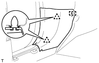
REMOVE REAR NO. 3 AIR DUCT
-
Remove the clip.
-
Fold back the floor carpet.
-
Detach the 2 claws and remove the rear No. 3 air duct.
-
-
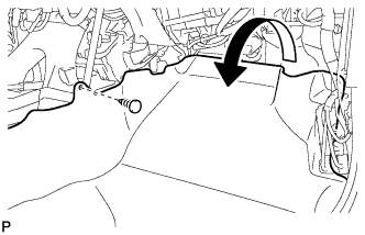
REMOVE REAR NO. 1 AIR DUCT
-
Remove the clip.
-
Fold back the floor carpet.
-
Detach the 2 claws and remove the rear No. 1 air duct.
-
-
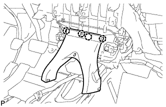
REMOVE NO. 1 AIR DUCT SUB-ASSEMBLY
-
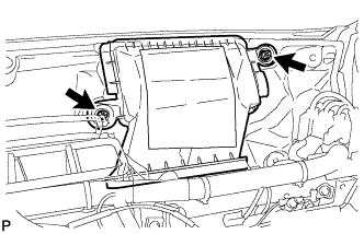
Remove the 2 nuts and No. 1 air duct sub-assembly.
-
-
REMOVE LOWER DEFROSTER NOZZLE ASSEMBLY
-
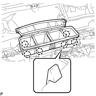
Detach the 6 claws and remove the lower defroster nozzle assembly.
-
-
REMOVE CENTER INSTRUMENT PANEL TO COWL BRACE
-
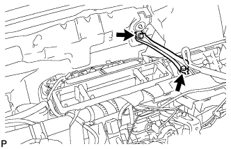
Remove the 2 bolts and center instrument panel to cowl brace.
-
-
REMOVE INSTRUMENT PANEL BRACE ASSEMBLY
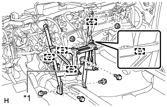
Text in Illustration *1 except Manual Transaxle
-
Disconnect the connector.
-
Detach each clamp.
-
Remove the 2 screws.
-
Remove the 3 bolts, 2 nuts and instrument panel brace assembly.
-
-
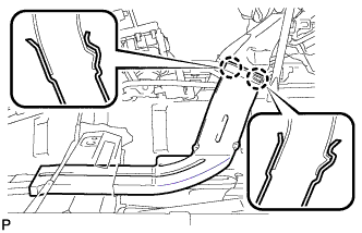
REMOVE REAR NO. 2 AIR DUCT
-
Detach the 4 claws and remove the rear No. 2 air duct.
-
-
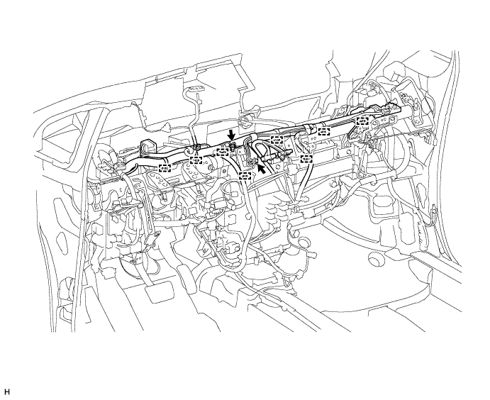
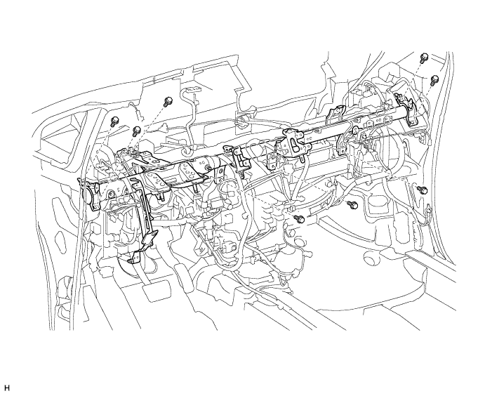
REMOVE INSTRUMENT PANEL REINFORCEMENT ASSEMBLY
-
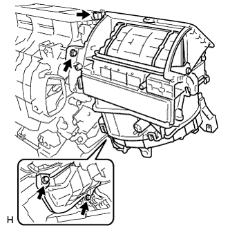
Remove the 2 bolts and ground wire.
-
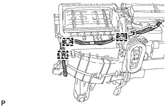
Detach each clamp and disconnect the wire harness.
-
Disconnect each connector.
-
Detach each clamp.
-
Remove each bolt, and disconnect the wire harness and junction block.
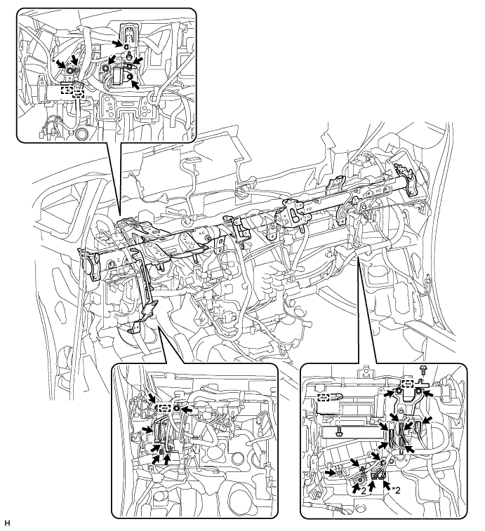
Text in Illustration *1 except Manual Transaxle *2 w/ PTC Heater -
Remove the 8 bolts and instrument panel reinforcement assembly.
-
-
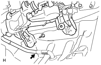
REMOVE AIR CONDITIONING UNIT
-
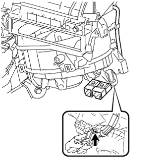
Disconnect the drain cooler hose.
-
Remove the bolt, nut and air conditioning unit.
Note
-
Be sure to support the air conditioning unit assembly when removing it because failure to do so may cause the bracket of the air conditioning unit assembly to break.
-
When removing the air conditioning unit, eliminate static electricity by touching the vehicle body to prevent the components from being damaged.
-
-
-
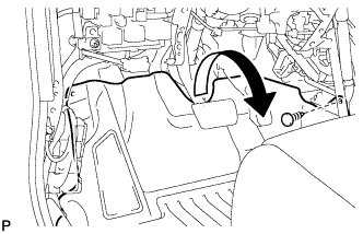
REMOVE NO. 2 AIR DUCT SUB-ASSEMBLY
-
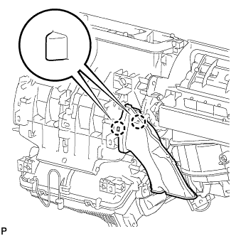
Detach the 2 claws and remove the No. 2 air duct sub-assembly.
-
-
REMOVE NO. 3 AIR DUCT SUB-ASSEMBLY
-
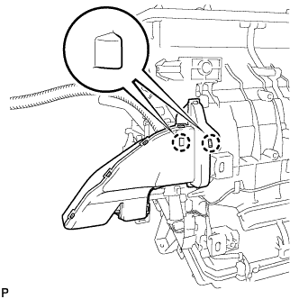
Detach the 2 claws and remove the No. 3 air duct sub-assembly.
-
-
REMOVE BLOWER ASSEMBLY
-
w/ PTC Heater:
Remove the screw.
-
w/ PTC Heater:
Detach the 3 clamps.
-
Disconnect the connector.
-
Remove the 3 screws and blower assembly.
-