COMBUSTION TYPE POWER HEATER SYSTEM Power Heater Alternator Circuit
DESCRIPTION
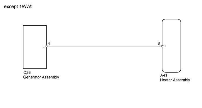
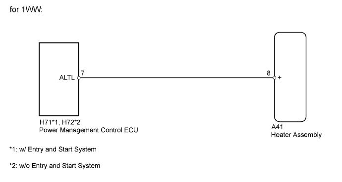
The ECU receives engine operation signals from the L terminal of the generator assembly*1 or power management control ECU*2. If this circuit is open or shorted, the ECU may incorrectly determine whether the engine is running or stopped. As a result, the heater assembly may not operate properly.
-
*1: except 1WW
-
*2: for 1WW
WIRING DIAGRAM
INSPECTION PROCEDURE
PROCEDURE
-
CHECK HARNESS AND CONNECTOR (HEATER ASSEMBLY - GENERATOR ASSEMBLY)
-
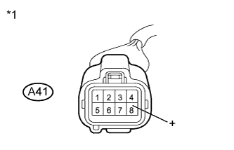
Text in Illustration *1 Front view of wire harness connector
(to Heater Assembly)
Disconnect the A41 heater connector.
-
Measure the voltage according to the value(s) in the table below.
Standard Voltage Tester Connection Condition Specified Condition A41-8 (+) - Body ground Engine running
(Generator operating)
11 to 14 V Result Result Proceed to OK (except 1WW) A OK (for 1WW) B NG C
B 
CHECK HARNESS AND CONNECTOR (HEATER ASSEMBLY - POWER MANAGEMENT CONTROL ECU) Click here
C 
REPAIR OR REPLACE HARNESS OR CONNECTOR
A 
-
-
CHECK HARNESS AND CONNECTOR (HEATER ASSEMBLY - GENERATOR)
-
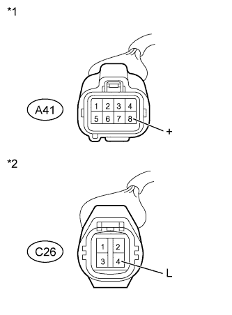
Text in Illustration *1 Front view of wire harness connector
(to Heater Assembly)
*2 Front view of wire harness connector
(to Generator Assembly)
Disconnect the A41 heater connector.
-
Disconnect the C26 generator connector.
-
Measure the resistance according to the value(s) in the table below.
Standard Resistance Tester Connection Condition Specified Condition A41-8 (+) - C26-4 (L) Always Below 1 Ω A41-8 (+) - Body ground Always 10 kΩ or higher
NG
REPAIR OR REPLACE HARNESS OR CONNECTOR
OK 
PROCEED TO NEXT SUSPECTED AREA SHOWN IN PROBLEM SYMPTOMS TABLE Click here
-
-
CHECK HARNESS AND CONNECTOR (HEATER ASSEMBLY - POWER MANAGEMENT CONTROL ECU)
-
w/ Entry and Start System:
-
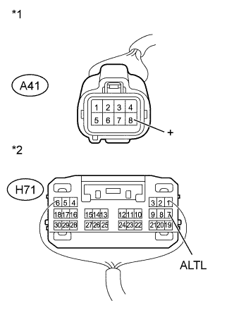
Text in Illustration *1 Front view of wire harness connector
(to Heater Assembly)
*2 Front view of wire harness connector
(to Power Management Control ECU)
Disconnect the A41 heater connector.
-
Disconnect the H71 power management control ECU connector.
-
Measure the resistance according to the value(s) in the table below.
Standard Resistance Tester Connection Condition Specified Condition A41-8 (+) - H71-7 (ALTL) Always Below 1 Ω A41-8 (+) - Body ground Always 10 kΩ or higher
-
-
w/o Entry and Start System:
-
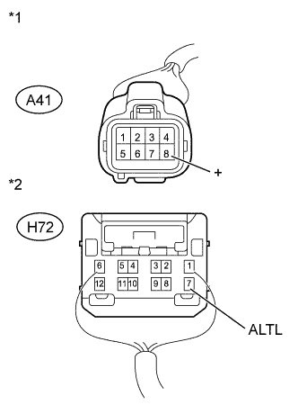
Text in Illustration *1 Front view of wire harness connector
(to Heater Assembly)
*2 Front view of wire harness connector
(to Power Management Control ECU)
Disconnect the A41 heater connector.
-
Disconnect the H72 power management control ECU connector.
-
Measure the resistance according to the value(s) in the table below.
Standard Resistance Tester Connection Condition Specified Condition A41-8 (+) - H72-7 (ALTL) Always Below 1 Ω A41-8 (+) - Body ground Always 10 kΩ or higher
-
NG
REPAIR OR REPLACE HARNESS OR CONNECTOR
OK
PROCEED TO NEXT SUSPECTED AREA SHOWN IN PROBLEM SYMPTOMS TABLE Click here
-