AIR CONDITIONING SYSTEM (for Manual Air Conditioning System) Heater Control Switch Circuit
DESCRIPTION
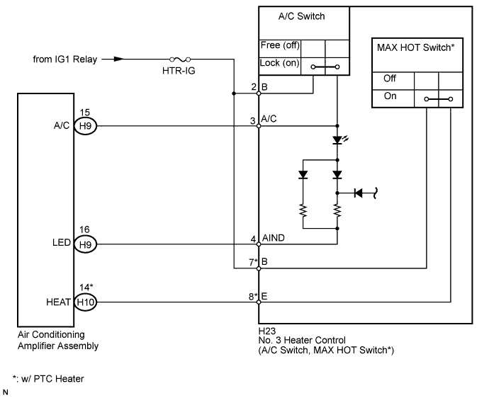
The No. 3 heater control sub-assembly is powered through the HTR-IG fuse. The No. 3 heater control sub-assembly transmits the operation signals of each switch to the air conditioning amplifier.
WIRING DIAGRAM
INSPECTION PROCEDURE
Note
Inspect the fuses for circuits related to this system before performing the following inspection procedure.
PROCEDURE
-
INSPECT NO. 3 HEATER CONTROL SUB-ASSEMBLY
-
Text in Illustration *1 w/ PTC Heater Remove the No. 3 heater control sub-assembly Click here.
-
Measure the resistance according to the value(s) in the table below.
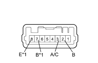
Standard Resistance Tester Connection Switch Condition Specified Condition 2 (B) - 3 (A/C) A/C switch on Below 1 Ω 2 (B) - 3 (A/C) A/C switch off 10 kΩ or higher 7 (B) - 8 (E)* Temperature setting MAX HOT Below 1 Ω 7 (B) - 8 (E)* Temperature setting not MAX HOT 10 kΩ or higher
-
*: w/ PTC heater
-
-
Apply battery voltage to the No. 3 heater control sub-assembly and check that the indicator light comes on.
OK Measurement Condition Specified Condition Battery positive (+) → Terminal 3
Battery negative (-) → Terminal 4
Indicator light comes on
NG 
REPLACE NO. 3 HEATER CONTROL SUB-ASSEMBLY Click here
OK 
-
-
CHECK HARNESS AND CONNECTOR (NO. 3 HEATER CONTROL - BATTERY)
-
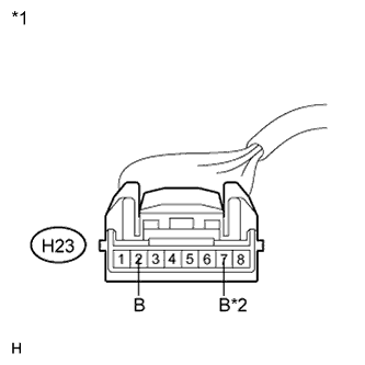
Text in Illustration *1 Front view of wire harness connector
(to No. 3 Heater Control Sub-assembly)
*2 w/ PTC Heater Disconnect the H23 heater control connector.
-
Measure the voltage according to the value(s) in the table below.
Standard Voltage Tester Connection Switch Condition Specified condition H23-2 (B) - Body ground Ignition switch ON 11 to 14 V H23-2 (B) - Body ground Ignition switch off Below 1 V H23-7 (B) - Body ground* Ignition switch ON 11 to 14 V H23-7 (B) - Body ground* Ignition switch off Below 1 V
-
*: w/ PTC heater
-
NG
REPAIR OR REPLACE HARNESS OR CONNECTOR
OK
-
-
CHECK HARNESS AND CONNECTOR (NO. 3 HEATER CONTROL - AIR CONDITIONING AMPLIFIER)
-
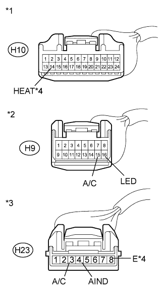
Text in Illustration *1 Front view of wire harness connector
(to Air Conditioning Amplifier Assembly)
*2 Front view of wire harness connector
(to Air Conditioning Amplifier Assembly)
*3 Front view of wire harness connector
(to No. 3 Heater Control Sub-assembly)
*4 w/ PTC Heater Disconnect the H10* and H9 amplifier connectors.
-
Disconnect the H23 heater control connector.
-
Measure the resistance according to the value(s) in the table below.
Standard Resistance Tester Connection Condition Specified condition H23-3 (A/C) - H9-15 (A/C) Always Below 1 Ω H23-4 (AIND) - H9-16 (LED) Always Below 1 Ω H23-8 (E) - H10-14 (HEAT)* Always Below 1 Ω H23-3 (A/C) - Body ground Always 10 kΩ or higher H23-4 (AIND) - Body ground Always 10 kΩ or higher H23-8 (E) - Body ground* Always 10 kΩ or higher
-
*: w/ PTC heater
-
NG
REPAIR OR REPLACE HARNESS OR CONNECTOR
OK 
PROCEED TO NEXT SUSPECTED AREA SHOWN IN PROBLEM SYMPTOMS TABLE Click here
-