AIR CONDITIONING SYSTEM (for Manual Air Conditioning System) Blower Motor Circuit
DESCRIPTION
When the heater control sub-assembly (blower switch) is operated, the HTR relay will turn on to allow current to flow to the blower with fan motor sub-assembly and then the motor will start rotating. Operating the heater control sub-assembly (blower switch) changes the current flow between the blower resistor and body ground, which changes the rotation speed of the blower with fan motor sub-assembly.
WIRING DIAGRAM

INSPECTION PROCEDURE
Note
Inspect the fuses for circuits related to this system before performing the following inspection procedure.
PROCEDURE
-
INSPECT RELAY (HTR)
-
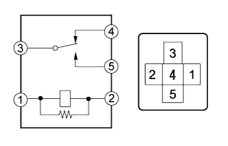
Remove the HTR relay from the instrument panel junction block.
-
Measure the resistance according to the value(s) in the table below.
Standard Resistance Tester Connection Condition Specified Condition 3 - 4 Battery voltage is not applied to terminals 1 and 2 Below 1 Ω 3 - 4 Battery voltage is applied to terminals 1 and 2 10 kΩ or higher 3 - 5 Battery voltage is not applied to terminals 1 and 2 10 kΩ or higher 3 - 5 Battery voltage is applied to terminals 1 and 2 Below 1 Ω
NG 
REPLACE RELAY (HTR)
OK 
-
-
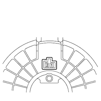
INSPECT BLOWER WITH FAN MOTOR SUB-ASSEMBLY
-
Remove the blower with fan motor sub-assembly Click here.
-
Apply battery voltage to the blower with fan motor sub-assembly and check the operation of the blower with fan motor sub-assembly.
OK Measurement Condition Specified Condition Battery positive (+) → Terminal 2
Battery negative (-) → Terminal 1
Blower with fan motor sub-assembly operation is normal
NG
REPLACE BLOWER WITH FAN MOTOR SUB-ASSEMBLY Click here
OK
-
-
INSPECT BLOWER RESISTOR
-
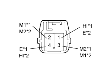
Text in Illustration *1 for LHD *2 for RHD Remove the blower resistor Click here.
-
Measure the resistance according to the value(s) in the table below.
Standard Resistance for LHD Tester Connection Condition Specified Condition 1 (HI) - 4 (E) Always 3.12 to 3.60 Ω 3 (M2) - 1 (HI) Always 0.52 to 0.60 Ω 2 (M1) - 1 (HI) Always 1.45 to 1.67 Ω for RHD Tester Connection Condition Specified Condition 4 (HI) - 1 (E) Always 3.12 to 3.60 Ω 2 (M2) - 4 (HI) Always 0.52 to 0.60 Ω 3 (M1) - 4 (HI) Always 1.45 to 1.67 Ω
NG
REPLACE BLOWER RESISTOR Click here
OK
-
-
INSPECT HEATER CONTROL SUB-ASSEMBLY (BLOWER SWITCH)
-
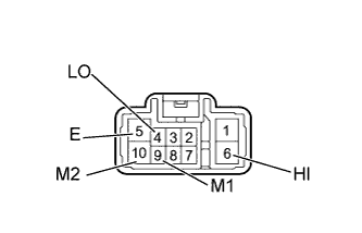
Remove the heater control sub-assembly (blower switch) Click here.
-
Measure the resistance according to the value(s) in the table below.
Standard Resistance Tester Connection Switch Condition Specified Condition 4 (LO), 6 (HI), 9 (M1) or 10 (M2) - 5 (E) Blower switch OFF 10 kΩ or higher 4 (LO) - 5 (E) Blower switch LO Below 1 Ω 4 (LO) or 9 (M1) - 5 (E) Blower switch M1 Below 1 Ω 4 (LO) or 10 (M2) - 5 (E) Blower switch M2 Below 1 Ω 4 (LO) or 6 (HI) - 5 (E) Blower switch HI Below 1 Ω
NG
REPLACE HEATER CONTROL SUB-ASSEMBLY (BLOWER SWITCH) Click here
OK
-
-
CHECK HARNESS AND CONNECTOR (AIR CONDITIONING AMPLIFIER ASSEMBLY - BATTERY)
-

Text in Illustration *1 Front view of wire harness connector
(to Air Conditioning Amplifier Assembly)
Disconnect the H118 amplifier connector.
-
Measure the voltage according to the value(s) in the table below.
Standard Voltage Tester Connection Switch Condition Specified Condition H118-14 (HR) - Body ground Ignition switch ON
Blower switch LO
Below 1 V H118-14 (HR) - Body ground Ignition switch ON
Blower switch OFF
11 to 14 V
NG
REPAIR OR REPLACE HARNESS OR CONNECTOR
OK
-
-
CHECK HARNESS AND CONNECTOR (HEATER CONTROL [BLOWER SWITCH] - BATTERY)
-
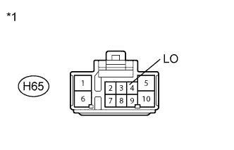
Text in Illustration *1 Front view of wire harness connector
(to Heater Control Sub-assembly [Blower Switch])
Disconnect the H65 heater control connector.
-
Measure the voltage according to the value(s) in the table below.
Standard Voltage Tester Connection Switch Condition Specified Condition H65-4 (LO) - Body ground Ignition switch ON 11 to 14 V H65-4 (LO) - Body ground Ignition switch off Below 1 V
NG
REPAIR OR REPLACE HARNESS OR CONNECTOR
OK
-
-
CHECK HARNESS AND CONNECTOR (BLOWER RESISTOR - HEATER CONTROL [BLOWER SWITCH])
-
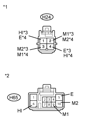
Text in Illustration *1 Front view of wire harness connector
(to Blower Resistor)
*2 Front view of wire harness connector
(to Heater Control Sub-assembly [Blower Switch])
*3 for LHD *4 for RHD Disconnect the H24 resistor connector.
-
Disconnect the H65 heater control connector.
-
Measure the resistance according to the value(s) in the table below.
Standard Resistance for LHD Tester Connection Condition Specified Condition H24-1 (HI) - H65-6 (HI) Always Below 1 Ω H24-3 (M2) - H65-10 (M2) Always Below 1 Ω H24-2 (M1) - H65-9 (M1) Always Below 1 Ω H24-4 (E) - Body ground Always Below 1 Ω H65-5 (E) - Body ground Always Below 1 Ω H24-1 (HI) - Body ground Always 10 kΩ or higher H24-3 (M2) - Body ground Always 10 kΩ or higher H24-2 (M1) - Body ground Always 10 kΩ or higher for RHD Tester Connection Condition Specified Condition H24-4 (HI) - H65-6 (HI) Always Below 1 Ω H24-2 (M2) - H65-10 (M2) Always Below 1 Ω H24-3 (M1) - H65-9 (M1) Always Below 1 Ω H24-1 (E) - Body ground Always Below 1 Ω H65-5 (E) - Body ground Always Below 1 Ω H24-4 (HI) - Body ground Always 10 kΩ or higher H24-2 (M2) - Body ground Always 10 kΩ or higher H24-3 (M1) - Body ground Always 10 kΩ or higher
NG
REPAIR OR REPLACE HARNESS OR CONNECTOR
OK
-
-
CHECK HARNESS AND CONNECTOR (BLOWER WITH FAN MOTOR - BLOWER RESISTOR AND HEATER CONTROL [BLOWER SWITCH])
-
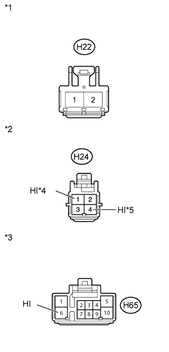
Text in Illustration *1 Front view of wire harness connector
(to Blower with Fan Motor Sub-assembly)
*2 Front view of wire harness connector
(to Blower Resistor)
*3 Front view of wire harness connector
(to Heater Control Sub-assembly [Blower Switch])
*4 for LHD *5 for RHD Disconnect the H22 blower connector.
-
Disconnect the H24 resistor connector.
-
Disconnect the H65 heater control connector.
-
Measure the resistance according to the value(s) in the table below.
Standard Resistance for LHD Tester Connection Condition Specified Condition H22-1 - H24-1 (HI) Always Below 1 Ω H22-1 - H65-6 (HI) Always Below 1 Ω H22-1 - Body ground Always 10 kΩ or higher for RHD Tester Connection Condition Specified Condition H22-1 - H24-4 (HI) Always Below 1 Ω H22-1 - H65-6 (HI) Always Below 1 Ω H22-1 - Body ground Always 10 kΩ or higher
NG
REPAIR OR REPLACE HARNESS OR CONNECTOR
OK
-
-
CHECK HARNESS AND CONNECTOR (BLOWER WITH FAN MOTOR - BATTERY)
-
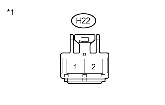
Text in Illustration *1 Front view of wire harness connector
(to Blower with Fan Motor Sub-assembly)
Disconnect the H22 blower connector.
-
Measure the voltage according to the value(s) in the table below.
Standard Voltage Tester Connection Switch Condition Specified Condition H22-2 - Body ground Ignition switch ON
Blower switch off
Below 1 V H22-2 - Body ground Ignition switch ON
Blower switch on
11 to 14 V
NG
REPAIR OR REPLACE HARNESS OR CONNECTOR
OK 
END
-