AIR CONDITIONING SYSTEM (for Manual Air Conditioning System) Recirculation Damper Servo Motor Circuit
DESCRIPTION
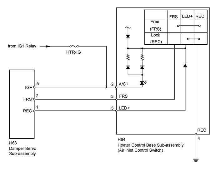
The damper servo sub-assembly and heater control base sub-assembly (air inlet control switch) are powered through the HTR-IG fuse. Operating the heater control base sub-assembly (air inlet control switch) drives the damper servo sub-assembly to switch between "FRESH" and "RECIRCULATION".
WIRING DIAGRAM
INSPECTION PROCEDURE
Note
Inspect the fuses for circuits related to this system before performing the following inspection procedure.
PROCEDURE
-
INSPECT DAMPER SERVO SUB-ASSEMBLY
-
Remove the damper servo sub-assembly Click here.
-
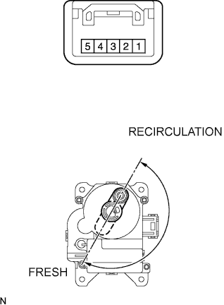
Apply battery voltage to the damper servo motor and check the operation of the damper servo sub-assembly.
OK Measurement Condition Specified Condition Battery positive (+) → Terminal 5
Battery negative (-) → Terminal 2
Arm turns to the "FRESH" side smoothly Battery positive (+) → Terminal 5
Battery negative (-) → Terminal 1
Arm turns to the "RECIRCULATION" side smoothly
NG 
REPLACE DAMPER SERVO SUB-ASSEMBLY Click here
OK 
-
-
CHECK HARNESS AND CONNECTOR (DAMPER SERVO - BATTERY)
-
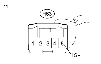
Text in Illustration *1 Front view of wire harness connector
(to Damper Servo Sub-assembly)
Disconnect the H63 servo connector.
-
Measure the voltage according to the value(s) in the table below.
Standard Voltage Tester Connection Switch Condition Specified Condition H63-5 (IG+) - Body ground Ignition switch off Below 1 V H63-5 (IG+) - Body ground Ignition switch ON 11 to 14 V
NG
REPAIR OR REPLACE HARNESS OR CONNECTOR
OK
-
-
CHECK HARNESS AND CONNECTOR (HEATER CONTROL BASE - BATTERY AND BODY GROUND)
-
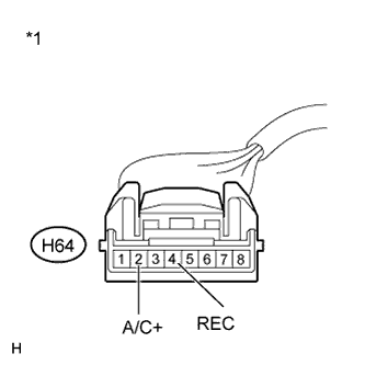
Text in Illustration *1 Front view of wire harness connector
(to Heater Control Base [Air Inlet Control Switch])
Disconnect the H64 heater control connector.
-
Measure the voltage according to the value(s) in the table below.
Standard Voltage Tester Connection Switch Condition Specified Condition H64-2 (A/C+) - Body ground Ignition switch off Below 1 V H64-2 (A/C+) - Body ground Ignition switch ON 11 to 14 V -
Measure the resistance according to the value(s) in the table below.
Standard Resistance Tester Connection Condition Specified Condition H64-4 (REC) - Body ground Always Below 1 Ω
NG
REPAIR OR REPLACE HARNESS OR CONNECTOR
OK
-
-
CHECK HARNESS AND CONNECTOR (HEATER CONTROL BASE - DAMPER SERVO)
-
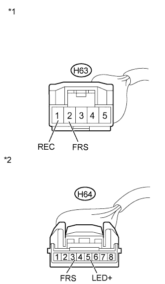
Text in Illustration *1 Front view of wire harness connector
(to Damper Servo Sub-assembly)
*2 Front view of wire harness connector
(to Heater Control Base [Air Inlet Control Switch])
Disconnect the H63 servo connector.
-
Disconnect the H64 heater control connector.
-
Measure the resistance according to the value(s) in the table below.
Standard Resistance Tester Connection Condition Specified Condition H64-3 (FRS) - H63-2 (FRS) Always Below 1 Ω H64-5 (LED+) - H63-1 (REC) Always Below 1 Ω H64-3 (FRS) - Body ground Always 10 kΩ or higher H64-5 (LED+) - Body ground Always 10 kΩ or higher
NG
REPAIR OR REPLACE HARNESS OR CONNECTOR
OK 
PROCEED TO NEXT SUSPECTED AREA SHOWN IN PROBLEM SYMPTOMS TABLE Click here
-