DESCRIPTION
The No. 1 cooler thermistor (evaporator temperature sensor) is installed on the evaporator in the air conditioning unit to detect the temperature of the cooled air that has passed through the evaporator and control the air conditioning. It sends appropriate signals to the air conditioning amplifier assembly. The resistance of the No. 1 cooler thermistor changes in accordance with the temperature of the cooled air that has passed through the evaporator. As the temperature decreases, the resistance increases. As the temperature increases, the resistance decreases.
The air conditioning amplifier assembly applies voltage (5 V) to the No. 1 cooler thermistor and reads voltage changes as the resistance of the No. 1 cooler thermistor changes. This sensor is used for frost prevention.
| DTC Code | DTC Detection Condition | Trouble Area |
|---|---|---|
| B1413 | An open or short in the No. 1 cooler thermistor circuit. |
|
INSPECTION PROCEDURE
PROCEDURE
- Click here
READ VALUE USING INTELLIGENT TESTER
-
Use the Data List to check if the No. 1 cooler thermistor is functioning properly.
Table 1. Air Conditioner Tester Display Measurement Item/Range Normal Condition Diagnostic Note Evaporator Fin Thermistor No. 1 cooler thermistor /
Min.: -29.7°C (-21.46°F)
Max.: 59.55°C (139.19°F)
Actual evaporator temperature displayed Open in the circuit: -29.7°C (-21.46°F).
Short in the circuit: 59.55°C (139.19°F).
Evaporator Target Temp Target evaporator temperature /
Min.: -327.68°C (-557.82°F)
Max.: 327.67°C (621.81°F)
Target evaporator temperature displayed - OK The display is as specified in the normal condition column. Table 2. Result Result Proceed to OK (When troubleshooting according to Problem Symptoms Table) A OK (When troubleshooting according to the DTC) B NG C
-
- Click here
INSPECT NO. 1 COOLER THERMISTOR
-
Remove the No. 1 cooler thermistor (Click here).
-
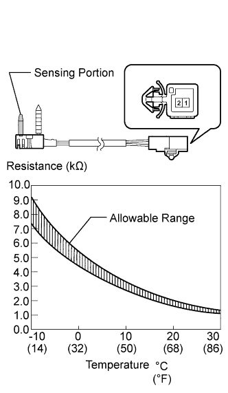
Measure the resistance according to the value(s) in the table below.
Standard Resistance Tester Connection Condition Specified Condition 1 - 2 -10°C (14°F) 7.30 to 9.10 kΩ -5°C (23°F) 5.65 to 6.95 kΩ 0°C (32°F) 4.40 to 5.35 kΩ 5°C (41°F) 3.40 to 4.15 kΩ 10°C (50°F) 2.70 to 3.25 kΩ 15°C (59°F) 2.14 to 2.58 kΩ 20°C (68°F) 1.71 to 2.05 kΩ 25°C (77°F) 1.38 to 1.64 kΩ 30°C (86°F) 1.11 to 1.32 kΩ Note:
-
Even slightly touching the sensor may change the resistance value. Be sure to hold the connector of the sensor.
-
When measuring, the sensor temperature must be the same as the ambient temperature.
Tip:As the temperature increases, the resistance decreases (refer to the graph).
Table 3. Result Result Proceed to OK (except 1WW Engine) A OK (for 1WW Engine) B NG C -
-
- Click here
CHECK HARNESS AND CONNECTOR (NO. 1 COOLER THERMISTOR - AIR CONDITIONING AMPLIFIER)
-
Disconnect the H45 thermistor connector.
-
Disconnect the H9 amplifier connector.
-
Measure the resistance according to the value(s) in the table below.
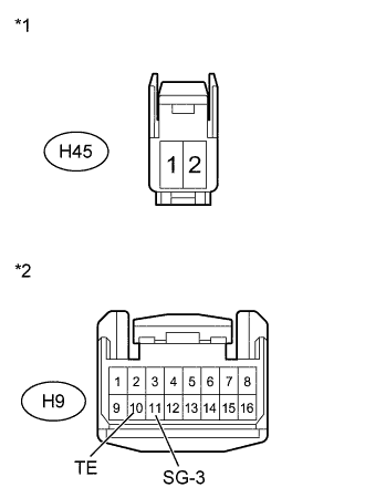
Standard Resistance Tester Connection Condition Specified Condition H9-10 (TE) - H45-1 Always Below 1 Ω H9-11 (SG-3) - H45-2 Always Below 1 Ω H9-10 (TE) - Body ground Always 10 kΩ or higher H9-11 (SG-3) - Body ground Always 10 kΩ or higher Table 4. Text in Illustration *1 Front view of wire harness connector
(to No. 1 Cooler Thermistor)
*2 Front view of wire harness connector
(to Air Conditioning Amplifier Assembly)
- OKClick here
- NGClick here
-
- Click here
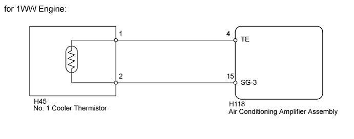
CHECK HARNESS AND CONNECTOR (NO. 1 COOLER THERMISTOR - AIR CONDITIONING AMPLIFIER)
-
Disconnect the H45 thermistor connector.
-
Disconnect the H118 amplifier connector.
-
Measure the resistance according to the value(s) in the table below.
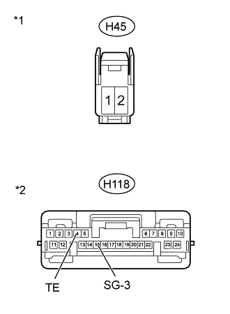
Standard Resistance Tester Connection Condition Specified Condition H118-4 (TE) - H45-1 Always Below 1 Ω H118-15 (SG-3) - H45-2 Always Below 1 Ω H118-4 (TE) - Body ground Always 10 kΩ or higher H118-15 (SG-3) - Body ground Always 10 kΩ or higher Table 5. Text in Illustration *1 Front view of wire harness connector
(to No. 1 Cooler Thermistor)
*2 Front view of wire harness connector
(to Air Conditioning Amplifier Assembly)
- OKClick here
- NGClick here
-
- Click here
REPLACE AIR CONDITIONING AMPLIFIER ASSEMBLYClick here
- Click here
REPLACE NO. 1 COOLER THERMISTORClick here
- Click here
REPAIR OR REPLACE HARNESS OR CONNECTOR
- Click here
PROCEED TO NEXT SUSPECTED AREA SHOWN IN PROBLEM SYMPTOMS TABLEClick here