AIR CONDITIONING SYSTEM (for Manual Air Conditioning System) Headlight Signal Circuit
DESCRIPTION
The air conditioning amplifier assembly receives the headlight illumination signal and uses the signal to judge electrical load conditions. The electrical load signal is one element of PTC heater control.
WIRING DIAGRAM
INSPECTION PROCEDURE
Note
Check that the headlight comes on when the light control switch is turned to the headlight position before proceeding to the inspection procedure.
PROCEDURE
-
CHECK HARNESS AND CONNECTOR (HEADLIGHT SIGNAL)
-
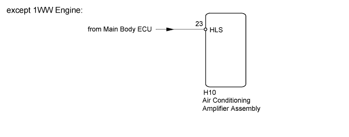
except 1WW Engine:
-
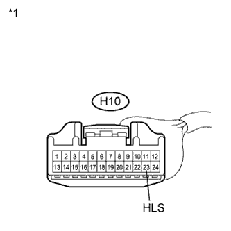
Text in Illustration *1 Front view of wire harness connector
(to Air Conditioning Amplifier Assembly)
Disconnect the H10 amplifier connector.
-
Measure the voltage according to the value(s) in the table below.
Standard Voltage Tester Connection Condition Specified Condition H10-23 (HLS) - Body ground Headlight dimmer switch off 11 to 14 V H10-23 (HLS) - Body ground Headlight dimmer switch on Below 1 V
-
-
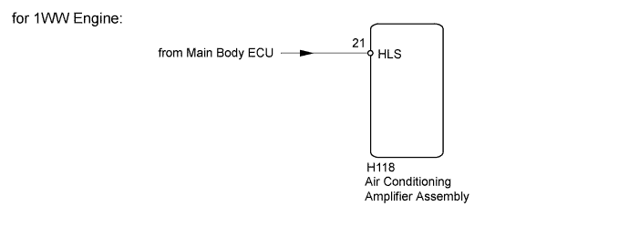
for 1WW Engine:
-
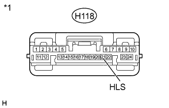
Text in Illustration *1 Front view of wire harness connector
(to Air Conditioning Amplifier Assembly)
Disconnect the H118 amplifier connector.
-
Measure the voltage according to the value(s) in the table below.
Standard Voltage Tester Connection Condition Specified Condition H118-21 (HLS) - Body ground Headlight dimmer switch off 11 to 14 V H118-21 (HLS) - Body ground Headlight dimmer switch on Below 1 V
-
NG 
REPAIR OR REPLACE HARNESS OR CONNECTOR
OK 
PROCEED TO NEXT SUSPECTED AREA SHOWN IN PROBLEM SYMPTOMS TABLE Click here
-