DESCRIPTION
When the ignition switch is turned to ON, the main body ECU transmits front seat inner belt LH*1 (or RH*2) state signals to the combination meter through the CAN. If the driver seat belt is not fastened, the combination meter blinks the driver side seat belt warning light. If the seat belt is fastened, the warning light goes off.
-
*1: for LHD
-
*2: for RHD
INSPECTION PROCEDURE
PROCEDURE
- Click here
CHECK FOR DTC (CAN COMMUNICATION SYSTEM)
-
Check if a CAN communication system DTC is output.
Table 1. Result Result Proceed to DTC is not output A CAN system DTC is output B
-
- Click here
PERFORM ACTIVE TEST USING INTELLIGENT TESTER (DRIVER SIDE SEAT BELT WARNING LIGHT)
-
Select the Active Test, use the intelligent tester to generate a control command, and then check that the driver side seat belt warning light turns on/off (Click here).
Table 2. Combination Meter Item Test Part Control Range Diagnostic Note Driver Side Seat Belt Driver side seat belt warning light ON/OFF Confirm that the vehicle is stopped and the engine is idling. OK Driver side seat belt warning light condition can be switched by Active Test.
- OKClick here
- NGClick here
-
- Click here
READ VALUE USING INTELLIGENT TESTER (DRIVER SIDE SEAT BELT BUCKLE SWITCH)
-
Check the Data List for proper functioning of the driver side seat belt buckle switch (Click here).
Table 3. Main Body Tester Display Measurement Item/Range Normal Condition Diagnostic Note D Seat Buckle SW Driver side seat belt buckle signal / ON or OFF ON: Driver side seat belt fastened
OFF: Driver side seat belt unfastened
- OK The display is as specified in the normal condition column.
- OKClick here
- NGClick here
-
- Click here
INSPECT FRONT SEAT INNER BELT ASSEMBLY
-
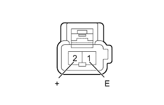
Remove the front seat inner belt (Click here).
-
Measure the resistance according to the value(s) in the table below.
Standard Resistance Tester Connection Condition Specified Condition 2 (+) - 1 (E) Driver side seat belt fastened 10 kΩ or higher Driver side seat belt unfastened Below 1 Ω
- OKClick here
- NGClick here
-
- Click here
CHECK HARNESS AND CONNECTOR (FRONT SEAT INNER BELT - MAIN BODY ECU AND BODY GROUND)
-
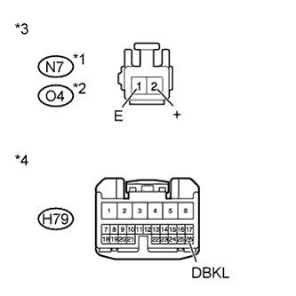
Disconnect the N7*1 or O4*2 front seat inner belt connector.
-
*1: for LHD
-
*2: for RHD
-
-
Disconnect the H79 ECU connector.
-
Measure the resistance according to the value(s) in the table below.
Standard Resistance Table 4. for LHD Tester Connection Condition Specified Condition N7-2 (+) - H79-26 (DBKL) Always Below 1 Ω N7-1 (E) - Body ground N7-2 (+) - Body ground Always 10 kΩ or higher Table 5. for RHD Tester Connection Condition Specified Condition O4-2 (+) - H79-26 (DBKL) Always Below 1 Ω O4-1 (E) - Body ground O4-2 (+) - Body ground Always 10 kΩ or higher Table 6. Text in Illustration *1 for LHD *2 for RHD *3 Front view of wire harness connector
(to Front Seat Inner Belt)
*4 Front view of wire harness connector
(to Main Body ECU)
- OKClick here
- NGClick here
-
- Click here
GO TO CAN COMMUNICATION SYSTEMClick here
- Click here
REPLACE COMBINATION METERClick here
- Click here
USE SIMULATION METHOD TO CHECKClick here
- Click here
REPLACE FRONT SEAT INNER BELT ASSEMBLYClick here
- Click here
REPAIR OR REPLACE HARNESS OR CONNECTOR
- Click here
REPLACE MAIN BODY ECU (INSTRUMENT PANEL JUNCTION BLOCK ASSEMBLY)