SEAT BELT WARNING SYSTEM TERMINALS OF ECU

-
CHECK COMBINATION METER ASSEMBLY

-
Disconnect the H62 combination meter assembly connector.
-
Measure the resistance and voltage according to the value(s) in the table below.
Terminal No. (Symbol) Wiring Color Terminal Description Condition Specified Condition H62-40 (B) - Body ground W - Body ground Battery power supply Always 11 to 14 V H62-39 (IG+) - Body ground P - Body ground IG power supply IG switch ON 11 to 14 V IG switch off Blow 1 V H62-21 (ET) - Body ground BR - Body ground Ground Always Below 1 Ω -
Reconnect the H62 combination meter assembly connector.
-
Measure the voltage according to the value(s) in the table below.
Terminal No. (Symbol) Wiring Color Terminal Description Condition Specified Condition H62-11 (PKBI) - Body ground L - Body ground*1
B - Body ground*2
Front passenger seat belt signal Front passenger seat occupied, seat belt fastened Below 1 V Front passenger seat occupied, seat belt unfastened 11 to 14 V H62-13 (MSD) - Body ground*3 R - Body ground Rear No. 1 seat belt LH signal Rear No. 1 seat belt LH fastened Below 1 V Rear No. 1 seat belt LH unfastened 11 to 14 V H62-14 (MSTI) - Body ground*3 W - Body ground Rear No. 1 seat center belt signal Rear No. 1 seat center belt fastened Below 1 V Rear No. 1 seat center belt unfastened 11 to 14 V H62-15 (MSFM) - Body ground*3 B - Body ground Rear No. 1 seat belt RH signal Rear No. 1 seat belt RH fastened Below 1 V Rear No. 1 seat belt RH unfastened 11 to 14 V H62-34 (MSM+) - Body ground*4 G - Body ground Rear No. 2 seat belt LH signal Rear No. 2 seat belt LH fastened Below 1 V Rear No. 2 seat belt LH unfastened 11 to 14 V H62-35 (MS+) - Body ground*4 L - Body ground Rear No. 2 seat belt RH signal Rear No. 2 seat belt RH fastened Below 1 V Rear No. 2 seat belt RH unfastened 11 to 14 V
-
*1: for RHD
-
*2: for LHD
-
*3: w/ Rear No. 1 Seat
-
*4: w/ Rear No. 2 Seat
-
-
-
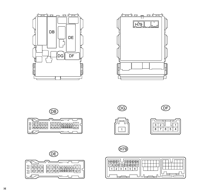
CHECK MAIN BODY ECU (INSTRUMENT PANEL JUNCTION BLOCK ASSEMBLY)
-
Disconnect the DB, DE, DF, DG and H79 main body ECU connectors.
-
Measure the resistance and voltage according to the value(s) in the table below.
Terminal No. (Symbol) Wiring Color Terminal Description Condition Specified Condition DE-28 (GND1) - Body ground W-B - Body ground Ground Always Below 1 Ω DG-1 (ALTB) - Body ground W - Body ground Battery (ECU power source) Always 11 to 14 V DB-30 (BECU) - Body ground W - Body ground Battery (ECU power source) Always 11 to 14 V DF-3 (IG) - Body ground W - Body ground IG power supply IG switch ON 11 to 14 V IG switch off Blow 1 V DF-5 (ACC) - Body ground W - Body ground ACC power supply IG switch ACC 11 to 14 V IG switch off Blow 1 V H79-8 (LCTY) - Body ground SB - Body ground Rear door courtesy light switch LH signal Rear LH door open Below 1 Ω Rear LH door closed 10 kΩ or higher DE-19 (RCTY) - Body ground LG - Body ground Rear door courtesy light switch RH signal Rear RH door open Below 1 Ω Rear RH door closed 10 kΩ or higher -
Reconnect the DB, DE, DF, DG and H79 main body ECU connectors.
-
Measure the voltage according to the value(s) in the table below.
Terminal No. (Symbol) Wiring Color Terminal Description Condition Specified Condition H79-26 (DBKL) - Body ground P - Body ground Driver seat belt warning signal Driver seat belt fastened 11 to 14 V Driver seat belt unfastened Below 1 V
-