- Click here
DISCONNECT CABLE FROM NEGATIVE BATTERY TERMINAL
CAUTION:Wait at least 90 seconds after disconnecting the cable from the negative (-) battery terminal to disable the SRS system.
Note:When disconnecting the cable, some systems need to be initialized after the cable is reconnected (Click here).
-
Click here
REMOVE NO. 1 INSTRUMENT PANEL UNDER COVER SUB-ASSEMBLY
-
Remove the 2 screws <A>.
-
Detach the claw and guide, and remove the No. 1 instrument panel under cover.
-
- Click here
REMOVE INSTRUMENT PANEL FINISH PANEL END LH
-
for Automatic Air Conditioning System:
-
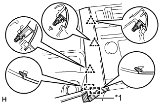
Put protective tape around the instrument panel finish panel end LH.
Table 1. Text in Illustration *1 Protective Tape -
Using a moulding remover A, detach the 3 clips and 2 guides, and remove the instrument panel finish panel end LH.
-
-
for Manual Air Conditioning System:
-
Put protective tape around the instrument panel finish panel end LH.
Table 2. Text in Illustration *1 Protective Tape -
Using a moulding remover A, detach the 3 clips and guide, and remove the instrument panel finish panel end LH.
-
-
-
Click here
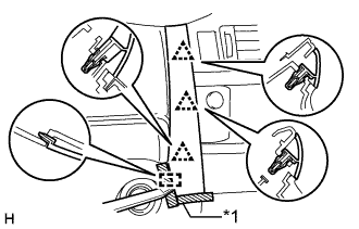
REMOVE INSTRUMENT PANEL FINISH PANEL END RH
-
for Automatic Air Conditioning System:
-
Put protective tape around the instrument panel finish panel end RH.
Table 3. Text in Illustration *1 Protective Tape -
Using a moulding remover A, detach the 3 clips, claw and 2 guides, and remove the instrument panel finish panel end RH.
-
-
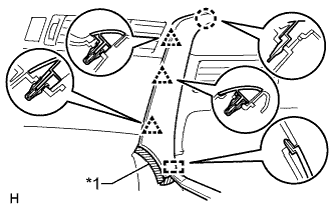
for Manual Air Conditioning System:
-
Put protective tape around the instrument panel finish panel end RH.
Table 4. Text in Illustration *1 Protective Tape -
Using a moulding remover A, detach the 3 clips, claw and guide, and remove the instrument panel finish panel end.
-
-
-
Click here
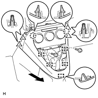
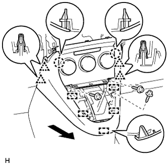
REMOVE CENTER INSTRUMENT PANEL REGISTER ASSEMBLY
-
Detach the 8 claws and 4 guides.
-
Disconnect the connector and remove the center instrument panel register.
-
- Click here
REMOVE RADIO RECEIVER ASSEMBLY (w/ Audio)
-
for Radio Receiver Type:
Remove the radio receiver assembly (Click here).
-
for Radio and Display Type:
Remove the radio receiver assembly (Click here).
-
-
Click here
REMOVE CENTER INSTRUMENT CLUSTER FINISH PANEL SUB-ASSEMBLY (w/o Audio)
-
Detach the 4 clips, 3 claws and 3 guides, and remove the center instrument cluster finish panel.
-
-
Click here
REMOVE STEREO OPENING COVER WITH BRACKET (w/o Audio)
-
Remove the 4 bolts and stereo opening cover.
-
- Click here
REMOVE SHIFT LEVER KNOB SUB-ASSEMBLY
-
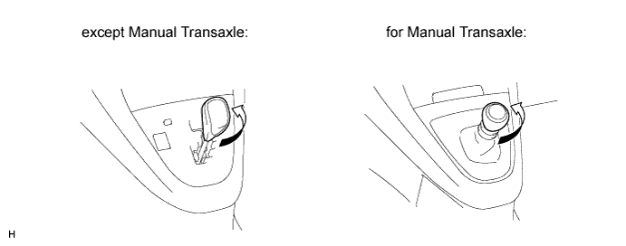
Twist the shift lever knob in the direction indicated by the arrow and remove it.
-
-
Click here
REMOVE POSITION INDICATOR HOUSING ASSEMBLY (except Manual Transaxle)
-
Detach the 5 claws and 3 clips.
-
Disconnect the connector and remove the position indicator housing.
-
-
Click here
REMOVE SHIFTING HOLE COVER (for Manual Transaxle)
-
Twist the T washer in the direction indicated by the arrow and remove it.
Table 5. Text in Illustration *1 T Washer -
Remove the knob spring.
-
Detach the 5 claws and 3 clips, and remove the shifting hole cover.
-
-
Click here
REMOVE LOWER CENTER INSTRUMENT PANEL FINISH PANEL (for Manual Transaxle)
-
for Automatic Air Conditioning System:
-
Remove the 2 screws <C>.
-
Detach the 2 claws, 4 clips and 5 guides, and remove the lower center instrument panel finish panel.
Tip:If the 2 claws shown in the illustration are difficult to detach, detach the 4 clips of the air conditioning control and remove the lower center instrument panel finish panel together with the air conditioning control.
-
-
for Manual Air Conditioning System:
-
Remove the 2 screws <C>.
-
Detach the 4 clips, 2 claws and 5 guides, and remove the lower center instrument panel finish panel.
-
-
-
Click here
REMOVE LOWER CENTER INSTRUMENT PANEL FINISH PANEL (except Manual Transaxle)
-
for Automatic Air Conditioning System:
-
Remove the 3 screws <C>.
-
Detach the 2 claws, 4 clips and 5 guides, and remove the lower center instrument panel finish panel.
Tip:If the 2 claws shown in the illustration are difficult to detach, detach the 4 clips of the air conditioning control and remove the lower center instrument panel finish panel together with the air conditioning control.
-
-
for Manual Air Conditioning System:
-
Remove the 3 screws <C>.
-
Detach the 4 clips, 2 claws and 5 guides, and remove the lower center instrument panel finish panel.
-
-
-
Click here
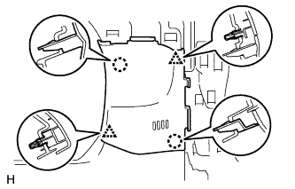
REMOVE NO. 2 SWITCH HOLE BASE
-
for LHD:
Detach the 5 claws and 5 clips, and remove the No. 2 switch hole base.
-
for RHD:
Detach the 3 claws and 5 clips, and remove the No. 2 switch hole base.
-
-
Click here
REMOVE NO. 1 SWITCH HOLE BASE
-
w/ Entry and Start System:
-
Detach the 2 claws and 2 clips.
-
Disconnect the connector and remove the No. 1 switch hole base.
-
-
w/o Entry and Start System:
-
Detach the 2 claws and 2 clips, and remove the No. 1 switch hole base.
-
-
- Click here
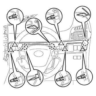
REMOVE STEERING COLUMN COVER
Note:Removing the steering column cover in an incorrect order will cause the steering column cover to break.
-
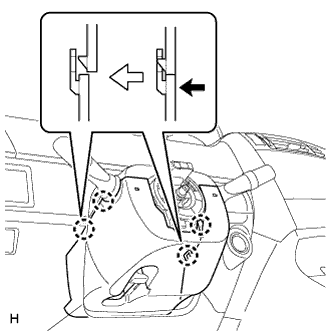
Push the right and left sides of the lower steering column cover and detach the 4 claws.
-
Insert fingers into the opening of the tilt lever of the lower steering column cover to detach the claw.
Tip:Spread the claw to detach it.
-
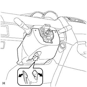
Using a screwdriver, disengage the 2 claws.
Table 6. Text in Illustration *1 Protective Tape -
Turn the steering column lower cover and remove the lower steering column cover as shown in the illustration.
-
- Click here
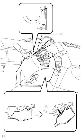
REMOVE LOWER NO. 1 INSTRUMENT PANEL AIRBAG ASSEMBLY
-
Remove the 4 bolts.
-
Detach the 6 claws and remove the instrument panel airbag.
-
Disconnect the connector.
Note:When handling the airbag connector, take care not to damage the airbag wire harness.
-