METER / GAUGE SYSTEM Tachometer Malfunction
DESCRIPTION
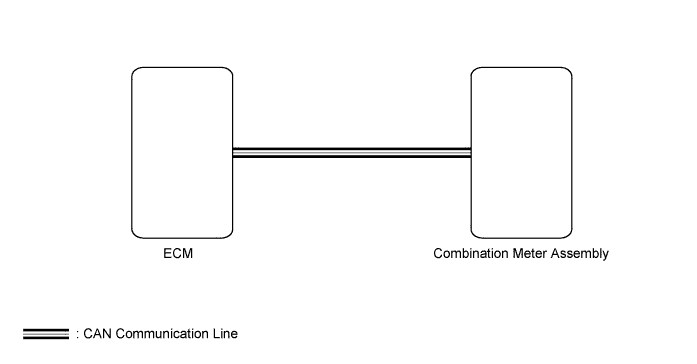
The combination meter receives engine speed signals from the ECM via the CAN line. The combination meter displays engine speed data that is calculated based on the data received from the ECM.
WIRING DIAGRAM
INSPECTION PROCEDURE
PROCEDURE
-
CHECK CAN COMMUNICATION SYSTEM
-
Check for DTCs Click here.
Result Result Proceed to CAN communication system DTC is not output A CAN communication system DTC is output B
B 
Go to CAN COMMUNICATION SYSTEM Click here
A 
-
-
PERFORM ACTIVE TEST USING INTELLIGENT TESTER (TACHOMETER)
-
Use the Active Test to check the operation of the tachometer Click here.
Combination Meter Tester Display Test Part Control Range Diagnostic Note TachoMeter Operation Tachometer 0, 1000, 2000, 3000, 4000, 5000, 6000 or 7000 Perform the test with the vehicle stopped and the engine idling. Tech Tips
Make sure that the vehicle is stopped and the engine is idling.
OK Needle indication is normal.
NG
REPLACE COMBINATION METER ASSEMBLY Click here
OK
-
-
READ VALUE USING INTELLIGENT TESTER (TACHOMETER)
-
Use the Data List to check if the tachometer is operating properly Click here.
Combination Meter Tester Display Measurement Item/Range Normal Condition Diagnostic Note Engine Rpm Engine speed/Min.: 0, Max.: 12750 Idling: 700 to 800 Unit: rpm OK Engine speed displayed on the intelligent tester is almost the same as the actual engine speed.
NG
REPLACE COMBINATION METER ASSEMBLY Click here
OK
-
-
READ VALUE USING INTELLIGENT TESTER (ENGINE SPEED)
-
Use the Data List to check the engine speed Click here.
Engine (for ZR Series Engine) Tester Display Measurement Item/Range Normal Condition Diagnostic Note Engine Speed Engine speed/Min.: 0, Max.: 16383 rpm
-
580 to 680 rpm: Idling (for Manual Transaxle)
-
600 to 700 rpm: Idling (except Manual Transaxle)
- Engine (for AD Series Engine) Tester Display Measurement Item/Range Normal Condition Diagnostic Note Engine Speed Engine speed/Min.: 0, Max.: 6000 rpm
-
50 to 400 rpm: Cranking
-
720 to 820 rpm: Idling with warm engine
When the crankshaft position sensor is malfunctioning, "Engine speed" is approximately 0 or varies greatly from the actual engine speed. Result Result Proceed to Engine speed displayed on intelligent tester is almost same as actual engine speed A Engine speed displayed on intelligent tester is not same as actual engine speed (for ZR Series Engine) B Engine speed displayed on intelligent tester is not same as actual engine speed (for AD Series Engine) C Tech Tips
-
for 1ZR-FAE:
If it is necessary to refer to the SFI system, refer to the following procedures Click here.
-
for 2ZR-FAE
If it is necessary to refer to the SFI system, refer to the following procedures Click here.
-
for 1AD-FTV, CCo:
If it is necessary to refer to the ECD system, refer to the following procedures Click here.
-
for 1AD-FTV, DPF:
If it is necessary to refer to the ECD system, refer to the following procedures Click here.
-
for 2AD-FHV:
If it is necessary to refer to the ECD system, refer to the following procedures Click here.
-
B
Go to SFI SYSTEM
C
Go to ECD SYSTEM
A
-
-
REPLACE COMBINATION METER ASSEMBLY
-
Temporarily replace the combination meter with a new one or normally functioning one Click here.
NEXT
-
-
CHECK COMBINATION METER ASSEMBLY
-
Check that the operation of the combination meter returns to normal Click here.
OK Operation of combination meter returns to normal. Result Result Proceed to OK A NG (for 1ZR-FAE) B NG (for 2ZR-FAE) C NG (for 1AD-FTV) D NG (for 2AD-FHV) E
B
REPLACE ECM Click here
C
REPLACE ECM Click here
D
REPLACE ECM Click here
E
REPLACE ECM Click here
A 
END (COMBINATION METER IS DEFECTIVE)
-