METER / GAUGE SYSTEM Entire Combination Meter does not Operate
DESCRIPTION
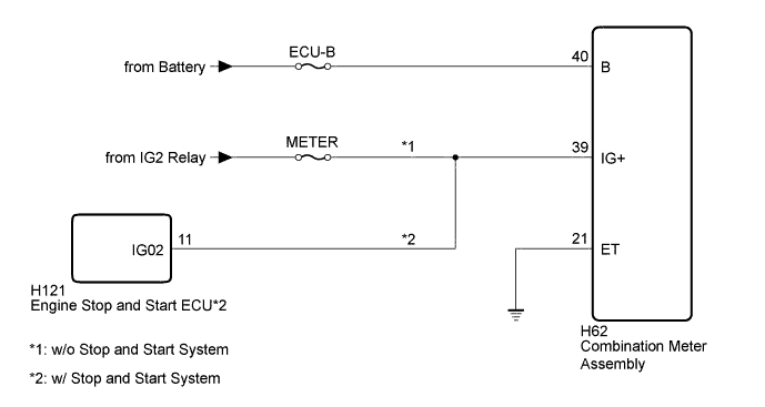
This circuit is the power source circuit for the meter. This circuit provides two types of power sources; one is a constant power source mainly used as a backup power source, and the other is an IG power source mainly used for signal transmission. The constant power source is mainly used as a backup power source for the meter CPU, however, it is also used for CAN communication. If a voltage of 12 V is not applied to terminal IG+ when the ignition switch is turned to ON, the combination meter does not operate.
WIRING DIAGRAM
INSPECTION PROCEDURE
Note
Inspect the fuses of circuits related to this system before performing the following procedure.
PROCEDURE
-
CHECK HARNESS AND CONNECTOR (COMBINATION METER ASSEMBLY - BATTERY AND BODY GROUND)
-
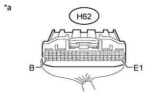
Text in Illustration *a Rear view of wire harness connector
(to Combination Meter Assembly)
Disconnect the combination meter assembly connector.
-
Measure the resistance according to the value(s) in the table below.
Standard Resistance Tester Connection Condition Specified Condition H62-21 (ET) - Body ground Always Below 1 Ω -
Measure the voltage according to the value(s) in the table below.
Standard Voltage Tester Connection Condition Specified Condition H62-40 (B) - Body ground Always 11 to 14 V
NG 
REPAIR OR REPLACE HARNESS OR CONNECTOR
OK 
-
-
CHECK HARNESS AND CONNECTOR (COMBINATION METER ASSEMBLY - BATTERY)
-
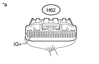
Text in Illustration *a Rear view of wire harness connector
(to Combination Meter Assembly)
Disconnect the combination meter assembly connector.
-
Measure the voltage according to the value(s) in the table below.
Standard Voltage Tester Connection Switch Condition Specified Condition H62-39 (IG+) - Body ground Ignition switch ON 11 to 14 V
NG 
CHECK HARNESS AND CONNECTOR (COMBINATION METER ASSEMBLY - ENGINE STOP AND START ECU) Click here
OK 
REPLACE COMBINATION METER ASSEMBLY Click here
-
-
CHECK HARNESS AND CONNECTOR (COMBINATION METER ASSEMBLY - ENGINE STOP AND START ECU)
-
Disconnect the H62 combination meter assembly connector.
-
Disconnect the H121 engine stop and start ECU connector.
-
Measure the resistance according to the value(s) in the table below.
Standard Resistance Tester Connection Condition Specified Condition H62-39 (IG+) - H121-1 (IG02) Always Below 1 Ω H62-39 (IG+) or H121-1 (IG02) - Body ground Always 10 kΩ or higher
NG
REPAIR OR REPLACE HARNESS OR CONNECTOR
OK
REPLACE ENGINE STOP AND START ECU Click here
-