DESCRIPTION
The main body ECU receives a No. 2 room light information signal from the back door courtesy light switch, and illuminates the No. 2 room light.
INSPECTION PROCEDURE
Inspect the fuses and bulbs for circuits related to this system before performing the following inspection procedure.
PROCEDURE
- Click here
READ VALUE USING INTELLIGENT TESTER (BACK DOOR COURTESY SWITCH)
-
Connect the intelligent tester to the DLC3.
-
Turn the ignition switch to ON.
-
Turn the intelligent tester on.
-
Enter the following menus: Body / Main Body / Data List / Back Door Courtesy Switch.
-
Use the Data List to check if the back door courtesy light switch is operating properly.
Table 1. Main Body Tester Display Measurement Item/Range Normal Condition Diagnostic Note Back Door Courtesy Switch Back door courtesy light switch / ON or OFF ON: Back door courtesy light switch on
OFF: Back door courtesy light switch off
- OK Tester display changes according to opening and closing of back door.
- OKClick here
- NGClick here
-
- Click here
INSPECT BACK DOOR LOCK ASSEMBLY (BACK DOOR COURTESY LIGHT SWITCH)
-
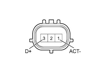
Remove the back door lock assembly (back door courtesy light switch) (Click here).
-
Measure the resistance according to the value(s) in the table below.
Standard Resistance Tester Connection Condition Specified Condition 1 (ACT-) - 3 (D+) Back door closed 10 kΩ or higher Back door opened Below 1 Ω
- OKClick here
- NGClick here
-
- Click here
CHECK HARNESS AND CONNECTOR (BACK DOOR LOCK ASSEMBLY - MAIN BODY ECU AND BODY GROUND)
-
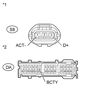
Disconnect the S8 back door lock assembly (back door courtesy light switch) connector.
-
Disconnect the DA main body ECU connector.
-
Measure the resistance according to the value(s) in the table below.
Standard Resistance Tester Connection Condition Specified Condition DA-7 (BCTY) - S8-3 (D+) Always Below 1 Ω S8-1 (ACT-) - Body ground Always Below 1 Ω S8-3 (D+) - Body ground Always 10 kΩ or higher Table 2. Text in Illustration *1 Front view of wire harness connector
(to Back Door Lock Assembly)
*2 Front view of wire harness connector
(to Main Body ECU)
- OKClick here
- NGClick here
-
- Click here
REPLACE MAIN BODY ECU (INSTRUMENT PANEL JUNCTION BLOCK ASSEMBLY)
- Click here
REPAIR OR REPLACE HARNESS OR CONNECTOR
- Click here
REPLACE BACK DOOR LOCK ASSEMBLY (BACK DOOR COURTESY LIGHT SWITCH)Click here
- Click here
PROCEED TO NEXT SUSPECTED AREA SHOWN IN PROBLEM SYMPTOMS TABLE