LIGHTING SYSTEM TERMINALS OF ECU

-
CHECK MAIN BODY ECU (INSTRUMENT PANEL JUNCTION BLOCK ASSEMBLY)
-
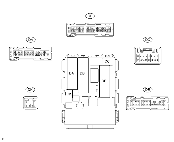
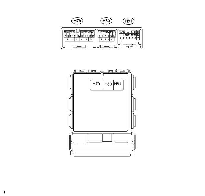
Disconnect the DB, DE and H80 main body ECU connectors.
-
Measure the voltage and resistance according to the value(s) in the table below.
Terminal No. (Symbol) Wiring Color Terminal Description Condition Specified Condition DB-30 (BECU) - Body ground W - Body ground Battery power supply Always 11 to 14 V DE-28 (GND1) - Body ground W-B - Body ground Body ground Always Below 1 Ω H80-4 (GND2) - Body ground W-B - Body ground Body ground Always Below 1 Ω If the result is not as specified, there may be a malfunction on the wire harness side.
-
Reconnect the DB, DE and H80 main body ECU connectors.
-
Measure the voltage according to the value(s) in the table below.
Terminal No. (Symbol) Wiring Color Terminal Description Condition Specified Condition DE-27 (ILE) - DE-28 (GND1) W-B - W-B Door mirror foot light signal Illumination on Below 1 V Illumination off 11 to 14 V DK-2 (ILE) - DE-28 (GND1) W - W-B Interior light signal Interior light on Below 1 V Interior light off 11 to 14 V H79-2 (FSPT) - DE-28 (GND1) W-B - W-B No. 1 interior illumination light signal No. 1 interior illumination light illumination on Below 1 V No. 1 interior illumination light illumination off 11 to 14 V H79-8 (LCTY) - DE-28 (GND1) SB - W-B Courtesy light switch signal
(Rear left door circuit)
Rear left door open Below 1 V Rear left door closed 11 to 14 V DA-21 (DCTY) - DE-28 (GND1)*1
DC-6 (DCTY) - DE-28 (GND1)*2
W - W-B*1
BR - W-B*2
Courtesy light switch signal
(Driver side door circuit)
Driver side door open Below 1 V Driver side door closed 11 to 14 V DE-19 (RCTY) - DE-28 (GND1) LG - W-B Courtesy light switch signal
(Rear right door circuit)
Rear right door open Below 1 V Rear right door closed 11 to 14 V DE-20 (PCTY) - DE-28 (GND1)*1
DA-24 (PCTY) - DE-28 (GND1)*2
BR - W-B*1
W - W-B*2
Courtesy light switch signal
(Front passenger side door circuit)
Front passenger side door open Below 1 V Front passenger side door closed 11 to 14 V DA-7 (BCTY) - DE-28 (GND1) LG - W-B Courtesy light switch signal
(Back door)
Back door open Below 1 V Back door closed 11 to 14 V H79-25 (LSWD) - DE-28 (GND1) Y - W-B*1
LG - W-B*2
Door lock position switch signal
(Driver side door)
Driver side door locked Below 1 V Driver side door unlocked 11 to 14 V
-
*1: for LHD
-
*2: for RHD
-
If the result is not as specified, the main body ECU may have a malfunction.
-
-