LIGHTING SYSTEM Illumination Circuit
DESCRIPTION
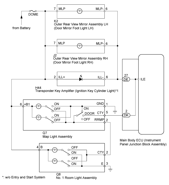
The main body ECU receives information regarding all the door courtesy light switches and door lock position switches, and turns on the room lights.
WIRING DIAGRAM
INSPECTION PROCEDURE
Tech Tips
Inspect the fuses and bulbs for circuits related to this system before performing the following inspection procedure.
PROCEDURE
-
PERFORM ACTIVE TEST USING INTELLIGENT TESTER
-
Connect the intelligent tester to the DLC3.
-
Turn the ignition switch to ON.
-
Turn the intelligent tester on.
-
Turn the map light switch to the DOOR position.
-
Close all the doors (all door courtesy light switches turn off).
-
Enter the following menus: Body / Main Body / Active Test / Illuminated Entry System.
-
Use the Active Test to check the operation of the illuminated entry system.
Main Body Tester Display Test Part Control Range Diagnostic Note Illuminated Entry System All parts illuminated by illuminated entry system ON/OFF - OK The illuminated entry system operates normally when operating it using the Active Test. Result Result Proceed to OK A NG (No lights turn on) B NG (Room lights do not turn on) C NG (Only ignition key cylinder light does not turn on)* D NG (Only door mirror foot lights do not turn on) E
-
*: w/o Entry and Start System
-
B 
PROCEED TO NEXT SUSPECTED AREA SHOWN IN PROBLEM SYMPTOMS TABLE Click here
C 
INSPECT MAP LIGHT ASSEMBLY Click here
D
INSPECT TRANSPONDER KEY AMPLIFIER (IGNITION KEY CYLINDER LIGHT) Click here
E
INSPECT OUTER REAR VIEW MIRROR ASSEMBLY (DOOR MIRROR FOOT LIGHT) Click here
A 
PROCEED TO NEXT SUSPECTED AREA SHOWN IN PROBLEM SYMPTOMS TABLE Click here
-
-
INSPECT MAP LIGHT ASSEMBLY
-
Remove the map light assembly Click here.
-
Measure the resistance according to the value(s) in the table below.
Standard Resistance Tester Connection Switch Condition Specified Condition 6 (+B1) - 5 (CTY) Map light switch off
Door switch not in door position
10 kΩ or higher 6 (+B1) - 5 (CTY) Map light switch off
Door switch in door position
Below 1 Ω 6 (+B1) - 1 (GND) Map light switch off
Door switch in on position
Below 1 Ω 6 (+B1) - 1 (GND) Map light switch off
Door switch not in on position
10 kΩ or higher 6 (+B1) - 1 (GND) Map light switch on Below 1 Ω 6 (+B1) - 2 (RRMP) Map light switch on
Door switch not in on position
10 kΩ or higher 6 (+B1) - 2 (RRMP) Map light switch off
Door switch not in on position
Below 1 Ω
NG
REPLACE MAP LIGHT ASSEMBLY Click here
OK 
-
-
CHECK HARNESS AND CONNECTOR (MAP LIGHT - MAIN BODY ECU, BATTERY AND BODY GROUND)
-
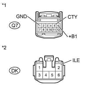
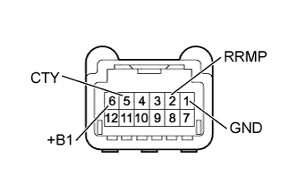
Text in Illustration *1 Front view of wire harness connector
(to Map Light Assembly)
*2 Front view of wire harness connector
(to Main Body ECU)
Disconnect the DK main body ECU connector.
-
Disconnect the Q7 map light connector.
-
Measure the voltage and resistance according to the value(s) in the table below.
Standard Voltage Tester Connection Condition Specified Condition Q7-6 (+B1) - Body ground Always 11 to 14 V Standard Resistance Tester Connection Condition Specified Condition Q7-5 (CTY) - DK-2 (ILE) Always Below 1 Ω Q7-5 (CTY) - Body ground Always 10 kΩ or higher Q7-1 (GND) - Body ground Always Below 1 Ω
NG
REPAIR OR REPLACE HARNESS OR CONNECTOR
OK
-
-
INSPECT NO. 1 ROOM LIGHT ASSEMBLY
-
Remove the No. 1 room light assembly Click here.
-
Measure the resistance according to the value(s) in the table below.
Standard Resistance Tester Connection Switch Condition Specified Condition 4 (B) - 3 (E) Off 10 kΩ or higher 4 (B) - 2 (CTY) Off Below 1 Ω 4 (B) - 3 (E) On Below 1 Ω 4 (B) - 2 (CTY) On 10 kΩ or higher
NG
REPLACE NO. 1 ROOM LIGHT ASSEMBLY Click here
OK
-
-
CHECK HARNESS AND CONNECTOR (NO. 1 ROOM LIGHT - MAP LIGHT, BATTERY AND BODY GROUND)
-
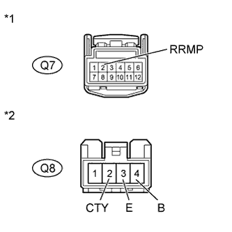
Text in Illustration *1 Front view of wire harness connector
(to Map Light Assembly)
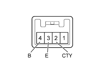
*2 Front view of wire harness connector
(to No. 1 Room Light Assembly)
Disconnect the Q7 map light connector.
-
Disconnect the Q8 No. 1 room light connector.
-
Measure the voltage and resistance according to the value(s) in the table below.
Standard Voltage Tester Connection Condition Specified Condition Q8-4 (B) - Body ground Always 11 to 14 V Standard Resistance Tester Connection Condition Specified Condition Q8-2 (CTY) - Q7-2 (RRMP) Always Below 1 Ω Q8-2 (CTY) - Body ground Always 10 kΩ or higher Q8-3 (E) - Body ground Always Below 1 Ω
NG
REPAIR OR REPLACE HARNESS OR CONNECTOR
OK
REPLACE MAIN BODY ECU (INSTRUMENT PANEL JUNCTION BLOCK ASSEMBLY)
-
-
INSPECT TRANSPONDER KEY AMPLIFIER (IGNITION KEY CYLINDER LIGHT)
-
Remove the transponder key amplifier (ignition key cylinder light) Click here.
-
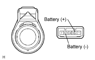
Connect the positive (+) lead from the battery to terminal 2 and the negative (-) lead to terminal 6, and check that the light comes on.
OK Light comes on.
NG
REPLACE TRANSPONDER KEY AMPLIFIER (IGNITION KEY CYLINDER LIGHT) Click here
OK
-
-
CHECK HARNESS AND CONNECTOR (TRANSPONDER KEY AMPLIFIER - BATTERY AND MAIN BODY ECU)
-
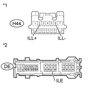
Text in Illustration *1 Front view of wire harness connector
(to Transponder Key Amplifier)
*2 Front view of wire harness connector
(to Main Body ECU)
Disconnect the H44 transponder key amplifier (ignition key cylinder light) connector.
-
Disconnect the DE main body ECU connector.
-
Measure the voltage and resistance according to the value(s) in the table below.
Standard Voltage Tester Connection Condition Specified Condition H44-2 (ILL+) - Body ground Always 11 to 14 V Standard Resistance Tester Connection Condition Specified Condition H44-6 (ILL-) - DE-27 (ILE) Always Below 1 Ω H44-6 (ILL-) - Body ground Always 10 kΩ or higher
NG
REPAIR OR REPLACE HARNESS OR CONNECTOR
OK
REPLACE MAIN BODY ECU (INSTRUMENT PANEL JUNCTION BLOCK ASSEMBLY)
-
-
INSPECT OUTER REAR VIEW MIRROR ASSEMBLY (DOOR MIRROR FOOT LIGHT)
-
Remove the outer rear view mirror assembly (door mirror foot light) Click here.
-
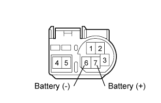
Connect the positive (+) lead from the battery to terminal 7 and the negative (-) lead to terminal 6, and check that the light comes on.
OK Light comes on.
NG
REPLACE OUTER REAR VIEW MIRROR ASSEMBLY (DOOR MIRROR FOOT LIGHT) Click here
OK
-
-
CHECK HARNESS AND CONNECTOR (OUTER REAR VIEW MIRROR ASSEMBLY - BATTERY AND MAIN BODY ECU)
-
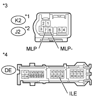
Text in Illustration *1 for LH *2 for RH *3 Front view of wire harness connector
(to Outer Rear View Mirror Assembly LH or RH)
*4 Front view of wire harness connector
(to Main Body ECU)
Disconnect the DE main body ECU connector.
-
Disconnect the K2*1 or J2*2 outer rear view mirror assembly (door mirror foot light) connector.
-
*1: for LH
-
*2: for RH
-
-
Measure the voltage and resistance according to the value(s) in the table below.
Standard Voltage for LH Tester Connection Condition Specified Condition K2-7 (MLP) - Body ground Always 11 to 14 V for RH Tester Connection Condition Specified Condition J2-7 (MLP) - Body ground Always 11 to 14 V Standard Resistance for LH Tester Connection Condition Specified Condition K2-6 (MLP-) - DE-27 (ILE) Always Below 1 Ω K2-6 (MLP-) - Body ground Always 10 kΩ or higher for RH Tester Connection Condition Specified Condition J2-6 (MLP-) - DE-27 (ILE) Always Below 1 Ω J2-6 (MLP-) - Body ground Always 10 kΩ or higher
NG
REPAIR OR REPLACE HARNESS OR CONNECTOR
OK
REPLACE MAIN BODY ECU (INSTRUMENT PANEL JUNCTION BLOCK ASSEMBLY)
-