THEFT DETERRENT SYSTEM Security Indicator Light Circuit
DESCRIPTION
-
When the theft deterrent system is in the disarmed state, the security indicator will flash continuously if the engine immobiliser system is set, or not illuminate if the engine immobiliser system is not set.
When the theft deterrent system is in the armed state, the engine immobiliser system is automatically set and the security indicator will flash continuously.
When the theft deterrent system is in the arming preparation state or alarm sounding state, the main body ECU (instrument panel junction block assembly) causes the security indicator to be illuminated.
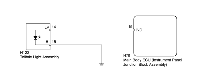
WIRING DIAGRAM
INSPECTION PROCEDURE
PROCEDURE
-
PERFORM ACTIVE TEST USING INTELLIGENT TESTER (SECURITY INDICATOR)
-
Operate the intelligent tester according to the steps on the display and select "Active Test" Click here.
Main Body Tester Display Test Part Control Range Diagnostic Note Security Indicator Security indicator ON/OFF - OK Security indicator illuminates.
NG 
INSPECT TELLTALE LIGHT ASSEMBLY (SECURITY INDICATOR) Click here
OK 
REPLACE MAIN BODY ECU (INSTRUMENT PANEL JUNCTION BLOCK ASSEMBLY)
-
-
INSPECT TELLTALE LIGHT ASSEMBLY (SECURITY INDICATOR)
-
Remove the telltale light assembly Click here.
-
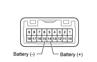
Connect the positive (+) lead from the battery to terminal 14 and the negative (-) lead to terminal 15, and check that the security indicator illuminates.
OK Security indicator illuminates.
NG 
REPLACE TELLTALE LIGHT ASSEMBLY (SECURITY INDICATOR) Click here
OK 
-
-
CHECK HARNESS AND CONNECTOR (TELLTALE LIGHT ASSEMBLY - MAIN BODY ECU AND BODY GROUND)
-
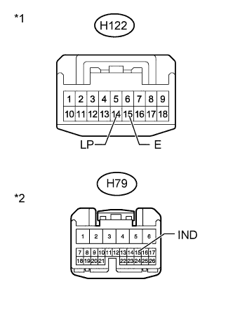
Text in Illustration *1 Front view of wire harness connector
(to Telltale Light Assembly)
*2 Front view of wire harness connector
(to Main Body ECU [Instrument Panel Junction Block Assembly])
Disconnect the H122 light connector.
-
Disconnect the H79 ECU connector.
-
Measure the resistance according to the value(s) in the table below.
Standard Resistance Tester Connection Condition Specified Condition H122-14 (LP) - H79-15 (IND) Always Below 1 Ω H122-15 (E) - Body ground Always Below 1 Ω H122-14 (LP) or H79-15 (IND) - Body ground Always 10 kΩ or higher
NG
REPAIR OR REPLACE HARNESS OR CONNECTOR
OK
REPLACE MAIN BODY ECU (INSTRUMENT PANEL JUNCTION BLOCK ASSEMBLY)
-