DESCRIPTION
This DTC is stored when one of the following occurs: 1) the ECM detects errors in its own communications with the transponder key ECU; 2) the ECM detects errors in the communication lines; or 3) the ECU - ECM communication ID between the transponder key ECU and ECM is different and an engine start is attempted. Before troubleshooting for this DTC, make sure no engine immobiliser DTCs are output. If output, troubleshoot the engine immobiliser DTCs first.
| DTC Code | DTC Detection Condition | Trouble Area |
|---|---|---|
| B2799 | One of the following conditions is met:
|
|
INSPECTION PROCEDURE
When the transponder key ECU and/or ECM is replaced, reregister the ECU - ECM communication ID.
PROCEDURE
- Click here
CLEAR DTC
-
Clear the DTCs (Click here).
- NEXTClick here
-
- Click here
CHECK FOR DTC
-
Check for DTCs (Click here).
OK DTC B2799 is not output.
- OKClick here
- NGClick here
-
- Click here
REREGISTER ECU - ECM COMMUNICATION ID
-
Reregister the ECU - ECM communication ID.
- NEXTClick here
-
- Click here
CLEAR DTC
-
Clear the DTCs (Click here).
- NEXTClick here
-
- Click here
CHECK FOR DTC
-
Check for DTCs (Click here).
OK DTC B2799 is not output.
- OKClick here
- NGClick here
-
- Click here
CHECK CONNECTION OF CONNECTOR
-
Turn the ignition switch off.
-
Check that the connectors are properly connected to the ECM and transponder key ECU.
OK Connectors are properly connected.
- OKClick here
- NGClick here
-
- Click here
CHECK HARNESS AND CONNECTOR (TRANSPONDER KEY ECU - ECM)
-
Disconnect the H110 ECU connector.
-
Disconnect the A51 ECM connector.
-
Measure the resistance according to the value(s) in the table below.
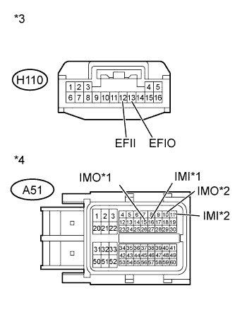
Standard Resistance for AD Series Engine Tester Connection Condition Specified Condition H110-13 (EFIO) - A51-16 (IMI) Always Below 1 Ω H110-12 (EFII) - A51-15 (IMO) H110-13 (EFIO) or A51-16 (IMI) - Body ground Always 10 kΩ or higher H110-12 (EFII) or A51-15 (IMO) - Body ground for ZR Series Engine Tester Connection Condition Specified Condition H110-13 (EFIO) - A51-11 (IMI) Always Below 1 Ω H110-12 (EFII) - A51-10 (IMO) H110-13 (EFIO) or A51-11 (IMI) - Body ground Always 10 kΩ or higher H110-12 (EFII) or A51-10 (IMO) - Body ground Table 1. Text in Illustration *1 for AD Series Engine *2 for ZR Series Engine *3 Front view of wire harness connector
(to Transponder Key ECU)
*4 Front view of wire harness connector
(to ECM)
- OKClick here
- NGClick here
-
- Click here
REPLACE TRANSPONDER KEY ECU
-
Temporarily replace the transponder key ECU with a new one.
- NEXTClick here
-
- Click here
CLEAR DTC
-
Clear the DTCs (Click here).
- NEXTClick here
-
- Click here
CHECK FOR DTC
-
Check for DTCs (Click here).
OK DTC B2799 is not output. Table 2. Result Result Proceed to OK A NG (for 1AD-FTV) B NG (for 2AD-FHV) C NG (for 1ZR-FAE) D NG (for 2ZR-FAE) E
-
- Click here
END (TRANSPONDER KEY ECU IS DEFECTIVE)
- Click here
USE SIMULATION METHOD TO CHECKClick here
- Click here
REPAIR OR REPLACE HARNESS OR CONNECTOR
- Click here
REPLACE ECMClick here
- Click here
CONNECT CONNECTOR CORRECTLY
- Click here
END
- Click here
REPLACE ECMClick here
- Click here
REPLACE ECMClick here
- Click here
REPLACE ECMClick here