ENTRY AND START SYSTEM (for Entry Function) Room Oscillator does not Recognize Key
DESCRIPTION
If the room oscillator does not recognize the key, one of the following may be the cause: 1) communication between the indoor electrical key oscillator (front floor) and electrical key transmitter cannot be performed; 2) communication between the indoor electrical key oscillator (rear floor) and electrical key transmitter cannot be performed; or 3) communication between the indoor electrical key oscillator (inside luggage) and electrical key transmitter cannot be performed.
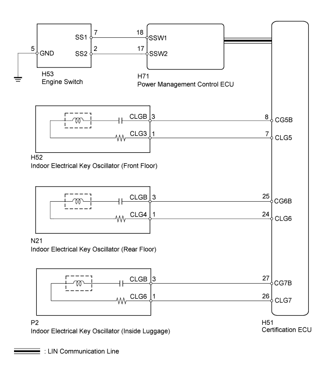
WIRING DIAGRAM
INSPECTION PROCEDURE
Note
-
Before performing the inspection, check that there are no problems related to the "CAN Communication System" and "LIN Communication System".
-
When using the intelligent tester with the engine switch off to troubleshoot: Connect the intelligent tester to the vehicle, and turn a courtesy light switch on and off at 1.5 second intervals until communication between the tester and vehicle begins.
PROCEDURE
-
CHECK ENTRY AND START SYSTEM (START FUNCTION)
-
Remove the battery of the electrical key transmitter Click here.
-
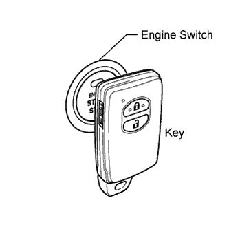
With the clutch pedal (for Manual Transaxle) or brake pedal (except Manual Transaxle) depressed, touch the TOYOTA mark of the key to the engine switch.
-
When operating the engine switch, check whether the power source mode changes.
OK Power source mode changes. Tech Tips
-
When the electrical key transmitter cannot be verified even though it is in the operating range of the start function, the engine start check can be performed by removing the transmitter battery from the electrical key transmitter and holding the transmitter against the engine switch.
-
When performing the check, if the power source mode changes, there is a problem with key certification inside the cabin.
-
NG 
CHECK HARNESS AND CONNECTOR (POWER MANAGEMENT CONTROL ECU - ENGINE SWITCH) Click here
OK 
-
-
CHECK WAVE ENVIRONMENT
-
Install the battery to the electrical key transmitter Click here.
-
Bring the electrical key transmitter near the indoor electrical key oscillator (front floor) and perform an engine control system start check.
Note
If the key is brought within 0.2 m (0.656 ft.) of the indoor electrical key oscillator (front floor), communication is not possible.
OK Engine starts. -
Bring the electrical key transmitter near the indoor electrical key oscillator (rear floor) and perform an engine control system start check.
Note
If the key is brought within 0.2 m (0.656 ft.) of the indoor electrical key oscillator (rear floor), communication is not possible.
OK Engine starts. -
Bring the electrical key transmitter near the indoor electrical key oscillator (inside luggage) and perform an engine control system start check.
Note
If the key is brought within 0.2 m (0.656 ft.) of the oscillator location inside the luggage area, communication is not possible.
Tech Tips
-
When the electrical key transmitter is brought near the indoor electrical key oscillator, the possibility of wave interference decreases, and it can be determined if wave interference is causing the problem symptom.
-
If the inspection result is that the operation check is normal, the possibility of wave interference is high. Also, added vehicle components may cause wave interference. If installed, remove them and perform the operation check.
-
NG
KEY DIAGNOSTIC MODE Click here
OK 
AFFECTED BY WAVE INTERFERENCE
-
-
KEY DIAGNOSTIC MODE
-
Diagnostic mode inspection (indoor electrical key oscillator [front floor]).
-
Connect the intelligent tester to the DLC3.
-
Turn the engine switch on (IG).
-
Turn the intelligent tester on.
-
Enter the following menus: Body / Entry&Start / Key Communication Check / Overhead + Front Room.
-
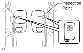
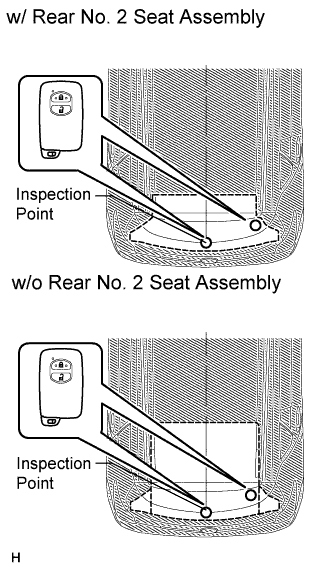
When the electrical key transmitter is in either of the 2 locations in the illustration, check that the wireless door lock buzzer sounds. Then repeat the check with the key in the other location.
-
-
Diagnostic mode inspection (indoor electrical key oscillator [rear floor]).
-
Connect the intelligent tester to the DLC3.
-
Turn the engine switch on (IG).
-
Turn the intelligent tester on.
-
Enter the following menus: Body / Entry&Start / Key Communication Check / Overhead + Rear Room.
-
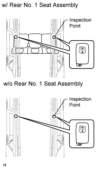
When the electrical key transmitter is in either of the 2 locations in the illustration, check that the wireless door lock buzzer sounds. Then repeat the check with the key in the other location.
-
-
Diagnostic mode inspection (indoor electrical key oscillator [inside luggage]).
-
Connect the intelligent tester to the DLC3.
-
Turn the engine switch on (IG).
-
Turn the intelligent tester on.
-
Enter the following menus: Body / Entry&Start / Key Communication Check / Overhead + Back Door (inside).
-
When the electrical key transmitter is in either of the 2 locations in the illustration, check that the wireless door lock buzzer sounds. Then repeat the check with the key in the other location.
Tech Tips
-
If the buzzer sounds, it can be determined that the vehicle interior transmitters are operating normally.
-
It is possible to check which indoor electrical key oscillator (front floor, rear floor or inside luggage) is operating by sounding the buzzer.
-
If the buzzer does not sound for any indoor electrical key oscillators, the certification ECU circuit may have a malfunction.
Result Result Proceed to Front operation check fails A Rear operation check fails B Luggage operation check fails C Front, rear and luggage operation checks are normal D Front, rear and luggage operation checks fail E -
B
CHECK HARNESS AND CONNECTOR (CERTIFICATION ECU - INDOOR ELECTRICAL KEY OSCILLATOR) Click here
C
CHECK HARNESS AND CONNECTOR (CERTIFICATION ECU - INDOOR ELECTRICAL KEY OSCILLATOR) Click here
D
INSPECT TRANSMITTER BATTERY (VOLTAGE) Click here
E 
REPLACE CERTIFICATION ECU
A
-
-
CHECK HARNESS AND CONNECTOR (CERTIFICATION ECU - INDOOR ELECTRICAL KEY OSCILLATOR)
-
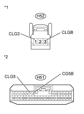
Text in Illustration *1 Front view of wire harness connector
(to Indoor Electrical Key Oscillator [Front Floor])
*2 Front view of wire harness connector
(to Certification ECU)
Disconnect the H51 ECU connector.
-
Disconnect the H52 oscillator connector.
-
Measure the resistance according to the value(s) in the table below.
Standard Resistance Tester Connection Condition Specified Condition H52-1 (CLG3) - H51-7 (CLG5) Always Below 1 Ω H52-3 (CLGB) - H51-8 (CG5B) Always Below 1 Ω H52-1 (CLG3) - Body ground Always 10 kΩ or higher H52-3 (CLGB) - Body ground Always 10 kΩ or higher
NG
REPAIR OR REPLACE HARNESS OR CONNECTOR
OK
-
-
CHECK INDOOR ELECTRICAL KEY OSCILLATOR (FRONT FLOOR)
-
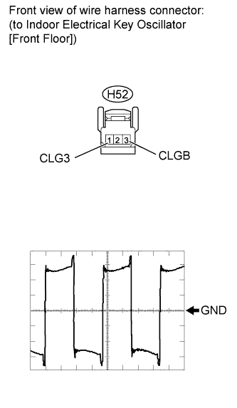
Disconnect the H52 oscillator connector.
-
Measure the voltage according to the value(s) in the table below.
Waveform (Reference) Item Content Tester Connection H52-1 (CLG3) - H52-3 (CLGB) Tool Setting 2 V/DIV, 2 μsec./DIV. (Reference) Condition Engine switch on (IG) OK Waveform is output normally (refer to illustration).
NG
REPLACE CERTIFICATION ECU
OK
-
-
REPLACE INDOOR ELECTRICAL KEY OSCILLATOR (FRONT FLOOR)
-
Temporarily replace the indoor electrical key oscillator (front floor) with a new or normally functioning one Click here.
NEXT
-
-
CHECK ENTRY AND START SYSTEM (FOR START FUNCTION)
-
Check that the engine switch indicator is illuminated in green, push the engine switch, and check that the engine starts.
OK Engine can be started.
NG
REPLACE CERTIFICATION ECU
OK
END (INDOOR ELECTRICAL KEY OSCILLATOR IS DEFECTIVE)
-
-
CHECK HARNESS AND CONNECTOR (CERTIFICATION ECU - INDOOR ELECTRICAL KEY OSCILLATOR)
-
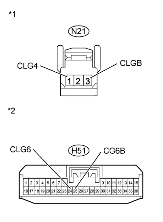
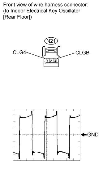
Text in Illustration *1 Front view of wire harness connector
(to Indoor Electrical Key Oscillator [Rear Floor])
*2 Front view of wire harness connector
(to Certification ECU)
Disconnect the H51 ECU connector.
-
Disconnect the N21 oscillator connector.
-
Measure the resistance according to the value(s) in the table below.
Standard Resistance Tester Connection Condition Specified Condition N21-1 (CLG4) - H51-24 (CLG6) Always Below 1 Ω N21-3 (CLGB) - H51-25 (CG6B) Always Below 1 Ω N21-1 (CLG4) - Body ground Always 10 kΩ or higher N21-3 (CLGB) - Body ground Always 10 kΩ or higher
NG
REPAIR OR REPLACE HARNESS OR CONNECTOR
OK
-
-
CHECK INDOOR ELECTRICAL KEY OSCILLATOR (REAR FLOOR)
-
Disconnect the N21 oscillator connector.
-
Measure the voltage according to the value(s) in the table below.
Waveform (Reference) Item Content Tester Connection H21-1 (CLG4) - H21-3 (CLGB) Tool Setting 2 V/DIV, 2 μsec./DIV. (Reference) Condition Engine switch on (IG) OK Waveform is output normally (refer to illustration).
NG
REPLACE CERTIFICATION ECU
OK
-
-
REPLACE INDOOR ELECTRICAL KEY OSCILLATOR (REAR FLOOR)
-
Temporarily replace the indoor electrical key oscillator (rear floor) with a new or normally functioning one Click here.
NEXT
-
-
CHECK ENTRY AND START SYSTEM (FOR START FUNCTION)
-
Check that the engine switch indicator is illuminated in green, push the engine switch, and check that the engine starts.
OK Engine can be started.
NG
REPLACE CERTIFICATION ECU
OK
END (INDOOR ELECTRICAL KEY OSCILLATOR IS DEFECTIVE)
-
-
CHECK HARNESS AND CONNECTOR (CERTIFICATION ECU - INDOOR ELECTRICAL KEY OSCILLATOR)
-
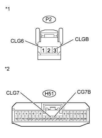
Text in Illustration *1 Front view of wire harness connector
(to Indoor Electrical Key Oscillator [Inside Luggage])
*2 Front view of wire harness connector
(to Certification ECU)
Disconnect the H51 ECU connector.
-
Disconnect the P2 oscillator connector.
-
Measure the resistance according to the value(s) in the table below.
Standard Resistance Tester Connection Condition Specified Condition P2-1 (CLG6) - H51-26 (CLG7) Always Below 1 Ω P2-3 (CLGB) - H51-27 (CG7B) Always Below 1 Ω P2-1 (CLG6) - Body ground Always 10 kΩ or higher P2-3 (CLGB) - Body ground Always 10 kΩ or higher
NG
REPAIR OR REPLACE HARNESS OR CONNECTOR
OK
-
-
CHECK INDOOR ELECTRICAL KEY OSCILLATOR (INSIDE LUGGAGE)
-
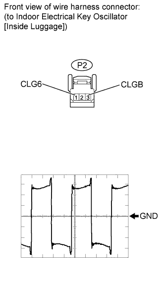
Disconnect the P2 oscillator connector.
-
Measure the voltage according to the value(s) in the table below.
Waveform (Reference) Item Content Tester Connection P2-1 (CLG6) - P2-3 (CLGB) Tool Setting 2 V/DIV, 2 μsec./DIV. (Reference) Condition Engine switch on (IG) OK Waveform is output normally (Refer to illustration).
NG
REPLACE CERTIFICATION ECU
OK
-
-
REPLACE INDOOR ELECTRICAL KEY OSCILLATOR (INSIDE LUGGAGE)
-
Temporarily replace the indoor electrical key oscillator (inside luggage) with a new or normally functioning one Click here.
NEXT
-
-
CHECK ENTRY AND START SYSTEM (FOR START FUNCTION)
-
Check that the engine switch indicator is illuminated in green, push the engine switch, and check that the engine starts.
OK Engine can be started.
NG
REPLACE CERTIFICATION ECU
OK
END (INDOOR ELECTRICAL KEY OSCILLATOR IS DEFECTIVE)
-
-
INSPECT TRANSMITTER BATTERY (VOLTAGE)
-
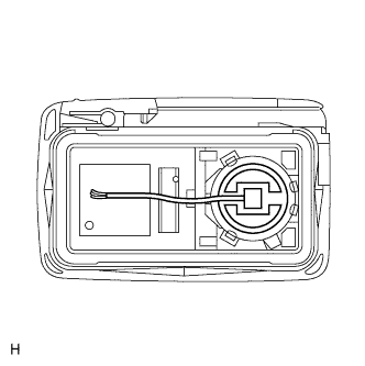
Remove the battery from the electrical key transmitter that does not operate Click here.
-
Attach a lead wire (0.6 mm (0.0236 in.) in diameter or less including wire sheath) with tape or equivalent to the negative terminal.
Note
Do not wrap the lead wire around a terminal, wedge it between terminals, or solder it. A terminal may be deformed or damaged, and the battery will not be able to be installed correctly.
-
Carefully pull the lead wire out from the position shown in the illustration and install the previously removed transmitter battery.
-
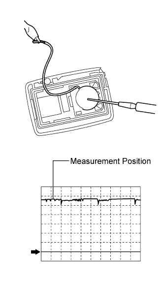
Using an oscilloscope, check the transmitter battery voltage waveform.
Tech Tips
When measuring the battery voltage, while operating the lock sensor of a door handle, bring the electrical key transmitter within the entry operating range to perform the measurement. For the entry operating range, refer to System Description Click here.
Standard Voltage Item Content Tester Connection Battery positive (+) - Battery negative (-) Tool Setting 0.5 V/DIV., 100 ms/DIV. Condition Engine switch off, all doors closed and lock switch pushed Specified Condition 2.5 to 3.2 V (Refer to the waveform)
NG
REPLACE TRANSMITTER BATTERY Click here
OK
-
-
CHECK ELECTRICAL KEY TRANSMITTER
-
Check if there is another registered transmitter available.
Result Result Proceed to Another registered transmitter is not available A Another registered transmitter is available B
B
CHECK ENTRY AND START SYSTEM Click here
A
-
-
REPLACE ELECTRICAL KEY TRANSMITTER
-
Replace the electrical key transmitter with a new or normally functioning one.
-
Perform the registration procedure (Refer to Service Bulletin for registration).
NEXT
-
-
CHECK ENTRY AND START SYSTEM
-
Check that the engine switch indicator is illuminated in green, push the engine switch, and check that the engine starts.
OK Engine can be started.
NG
REPLACE CERTIFICATION ECU
OK
END (ELECTRICAL KEY TRANSMITTER IS DEFECTIVE)
-
-
CHECK HARNESS AND CONNECTOR (POWER MANAGEMENT CONTROL ECU - ENGINE SWITCH)
-
Disconnect the H71 connector.
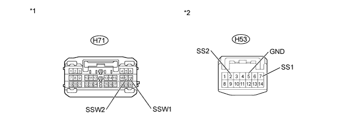
-
Disconnect the H53 switch connector.
-
Measure the resistance according to the value(s) in the table below.
Standard Resistance Tester Connection Condition Specified Condition H53-7 (SS1) - H71-18 (SSW1) Always Below 1 Ω H53-2 (SS2) - H71-17 (SSW2) Always Below 1 Ω H53-7 (SS1) - Body ground Always 10 kΩ or higher H53-2 (SS2) - Body ground Always 10 kΩ or higher H53-5 (GND) - Body ground Always Below 1 Ω Text in Illustration *1 Front view of wire harness connector
(to Power Management Control ECU)
*2 Front view of wire harness connector
(to Engine Switch)
NG
REPAIR OR REPLACE HARNESS OR CONNECTOR
OK
-
-
INSPECT ENGINE SWITCH
-
for 1AD-FTV:
-
Remove the engine switch Click here.
-
-
for 2AD-FHV:
-
Remove the engine switch Click here.
-
-
for 1ZR-FAE:
-
Remove the engine switch Click here.
-
-
for 2ZR-FAE:
-
Remove the engine switch Click here.
-
-
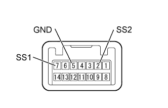
Measure the resistance according to the value(s) in the table below.
Standard Resistance Tester Connection Switch Condition Specified Condition 7 (SS1) - 5 (GND) Engine switch pushed Below 1 Ω Engine switch not pushed 10 kΩ or higher 2 (SS2) - 5 (GND) Engine switch pushed Below 1 Ω Engine switch not pushed 10 kΩ or higher Result Result Proceed to OK (for LHD) A OK (for RHD) B NG C Tech Tips
-
Engine switch replacement procedure:
-
for 1AD-FTV Click here
-
for 2AD-FHV Click here
-
for 1ZR-FAE Click here
-
for 2ZR-FAE Click here
-
B
REPLACE POWER MANAGEMENT CONTROL ECU Click here
C
REPLACE ENGINE SWITCH
A
REPLACE POWER MANAGEMENT CONTROL ECU Click here
-