ENTRY AND START SYSTEM (for Entry Function), Diagnostic DTC:B27A1

| DTC Code | DTC Name |
|---|---|
| B27A1 | Open in Driver Side Electrical Antenna Circuit |
DESCRIPTION
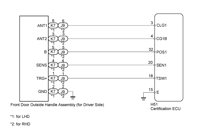
The certification ECU generates a request signal and transmits the signal to the front door outside handle assembly (for driver side) at an interval of 250 ms. The front door outside handle assembly (for driver side) detects when the electrical key is brought close to the vehicle, and when a request signal is received from within 1.0 m (3.28 ft.) of the driver door, the signal is transmitted at the frequency stated above. DTC B27A1 is stored by the certification ECU when an open circuit is detected in the circuit between the certification ECU and the front door outside handle assembly (for driver side) (CLG1 - ANT1, CG1B - ANT2).
| DTC Code | DTC Detection Condition | Trouble Area |
|---|---|---|
| B27A1 | An open circuit is detected in the circuit between the certification ECU and front door outside handle assembly (for driver side) (CLG1 - ANT1, CG1B - ANT2). |
|
WIRING DIAGRAM
INSPECTION PROCEDURE
Note
When using the intelligent tester with the engine switch off to troubleshoot: Connect the intelligent tester to the DLC3, and turn a courtesy light switch on and off at 1.5-second intervals until communication between the tester and vehicle begins.
PROCEDURE
-
CHECK CONNECTOR CONNECTION CONDITION
-
Turn the engine switch off.
-
Check that the connectors are properly connected to the certification ECU and front door outside handle assembly (for driver side).
OK Connectors are properly connected.
NG 
CONNECT CONNECTORS PROPERLY
OK 
-
-
CHECK HARNESS AND CONNECTOR (OUTSIDE DOOR HANDLE ASSEMBLY - CERTIFICATION ECU)
-
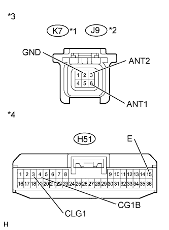
Text in Illustration *1 for LHD *2 for RHD *3 Front view of wire harness connector
(to Front Door Outside Handle Assembly [for Driver Side])
*4 Front view of wire harness connector
(to Certification ECU)
Disconnect the H51 ECU connector.
-
Disconnect the K7*1 or J9*2 handle connector.
-
*1: for LHD
-
*2: for RHD
-
-
Measure the resistance according to the value(s) in the table below.
Standard Resistance for LHD Tester Connection Condition Specified Condition K7-3 (ANT2) - H51-4 (CG1B) Always Below 1 Ω K7-6 (ANT1) - H51-3 (CLG1) Always Below 1 Ω K7-2 (GND) - Body ground Always Below 1 Ω H51-4 (CG1B) - Body ground Always 10 kΩ or higher H51-3 (CLG1) - Body ground Always 10 kΩ or higher H51-15 (E) - Body ground Always Below 1 Ω for RHD Tester Connection Condition Specified Condition J9-3 (ANT2) - H51-4 (CG1B) Always Below 1 Ω J9-6 (ANT1) - H51-3 (CLG1) Always Below 1 Ω J9-2 (GND) - Body ground Always Below 1 Ω H51-4 (CG1B) - Body ground Always 10 kΩ or higher H51-3 (CLG1) - Body ground Always 10 kΩ or higher H51-15 (E) - Body ground Always Below 1 Ω
NG
REPAIR OR REPLACE HARNESS OR CONNECTOR
OK
-
-
CHECK CERTIFICATION ECU
-
Measure the voltage according to the value(s) in the table below.
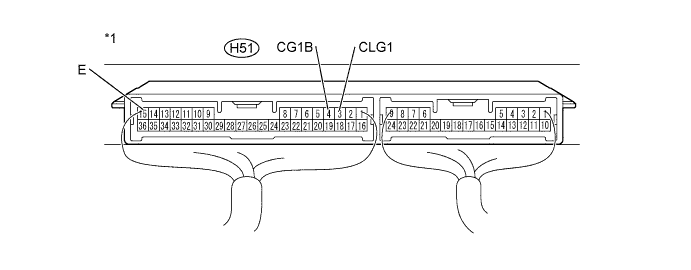
Standard Voltage Tester Connection Switch Condition Specified Condition H51-3 (CLG1) - H51-15 (E) Engine switch off, all doors closed, and key not in cabin No pulse generation H51-3 (CLG1) - H51-15 (E) Engine switch off, all doors closed, all doors locked with wireless door lock control and key not in cabin Pulse generation H51-4 (CG1B) - H51-15 (E) Engine switch off, all doors closed, and key not in cabin No pulse generation H51-4 (CG1B) - H51-15 (E) Engine switch off, all doors closed, all doors locked with wireless door lock control and key not in cabin Pulse generation Text in Illustration *1 Component with harness connected
(Certification ECU)
- -
NG
REPLACE CERTIFICATION ECU
OK
-
-
REPLACE FRONT DOOR OUTSIDE HANDLE ASSEMBLY (FOR DRIVER SIDE)
-
Temporarily replace the front door outside handle assembly (for driver side) with a new or normally functioning one Click here.
NEXT
-
-
CHECK FOR DTC
-
Clear the DTCs Click here.
-
Check for DTCs Click here.
OK DTC B27A1 is not output.
NG
REPLACE CERTIFICATION ECU
OK 
END (FRONT DOOR OUTSIDE HANDLE ASSEMBLY IS DEFECTIVE)
-