FRONT DOOR LOCK INSTALLATION

Tech Tips
-
Use the same procedure for the RH and LH sides.
-
The procedure listed below is for the LH side.
-
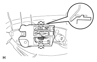
INSTALL FRONT DOOR INSIDE LOCKING CABLE ASSEMBLY LH
-
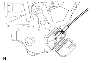
Install the front door inside locking cable assembly.
-
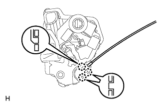
Attach the 3 claws.
-
-
INSTALL FRONT DOOR LOCK REMOTE CONTROL CABLE ASSEMBLY LH
-
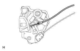
Install the front door lock remote control cable.
-
-
INSTALL FRONT DOOR LOCK ASSEMBLY LH
Note
-
When reusing the removed front door lock assembly, replace the door lock wiring harness seal on the connector with a new one.
-
Do not allow grease or dust to adhere to the surface of the connector which contacts the door lock wiring harness seal.
-
Reusing the door lock wiring harness seal or using a damaged door lock wiring harness seal may allow water into the connection. This may result in a malfunction of the front door lock assembly.
-
Apply MP grease to the sliding parts of the front door lock assembly.
-
Install a new door lock wiring harness seal to the front door lock assembly.
-
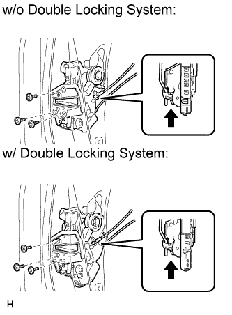
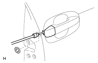
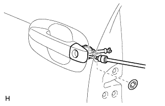
Insert the front door lock open rod into the front door lock assembly.
-
Check that the front door lock open rod is securely connected to the front door lock assembly.
-
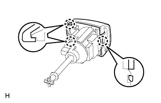
Using a T30 "TORX" wrench, install the front door lock assembly with the 3 screws.
- Torque:
- 5.0 N*m { 51 kgf*cm, 44 in.*lbf }
-
-
INSTALL FRONT DOOR OUTSIDE HANDLE COVER RH (for Front Passenger Side)
-
Tighten the screw using a T30 "TORX" socket to install the cover.
- Torque:
- 4.0 N*m { 41 kgf*cm, 35 in.*lbf }
-
Install the hole plug.
-
-
INSTALL FRONT DOOR OUTSIDE HANDLE COVER LH (for Driver Side)
-
Attach the 3 claws to install the front door outside handle cover to the front door lock key cylinder.
-
Tighten the screw using a T30 "TORX" socket to install the cover (with the door lock key cylinder).
- Torque:
- 4.0 N*m { 41 kgf*cm, 35 in.*lbf }
-
Install the hole plug.
-
-
INSTALL FRONT DOOR REAR LOWER FRAME SUB-ASSEMBLY LH
-
Install the rear lower frame with the bolt.
- Torque:
- 6.2 N*m { 63 kgf*cm, 55 in.*lbf }
-
-
INSTALL FRONT DOOR GLASS RUN LH
-
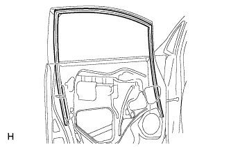
Install the front door glass run.
-
-
INSTALL FRONT DOOR GLASS SUB-ASSEMBLY LH
-
for Driver Side:
Temporarily install the master switch assembly.
-
for Front Passenger Side:
Temporarily install the regulator switch assembly.
-
Connect the cable to the negative (-) battery terminal.
-
Move the door glass until the bolts appear in the service holes.
-
Disconnect the cable from the negative (-) battery terminal.
Note
When disconnecting the cable, some systems need to be initialized after the cable is reconnected Click here.
-
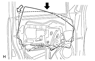
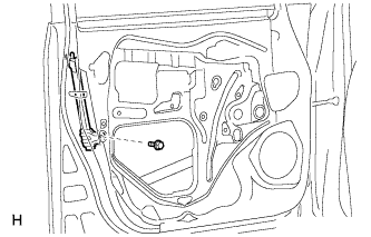
Insert the door glass into the door panel along the glass run as indicated by the arrows in the illustration.
Note
Be careful not to damage the glass.
-
Install the door glass to the window regulator with the 2 bolts.
- Torque:
- 8.0 N*m { 82 kgf*cm, 71 in.*lbf }
-
-
INSTALL FRONT DOOR SERVICE HOLE COVER LH
-
Apply butyl tape to the door.
-
Pass the front door lock remote control cable and front door inside locking cable through a new front door service hole cover.
-
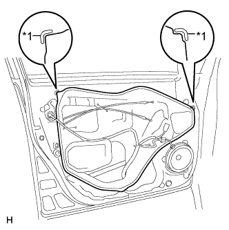
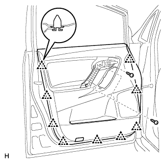
Text in Illustration *1 Reference Point Install the front door service hole cover according to the reference points on the front door panel.
Note
-
Securely install the front door service hole cover to prevent wrinkles and air bubbles.
-
There should be no wrinkles or folds after installing the service hole cover.
-
After installing the service hole cover, check the seal quality.
-
-
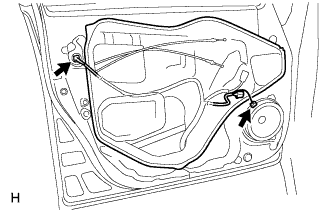
Connect the 2 connectors.
-
-
INSTALL FRONT DOOR INNER GLASS WEATHERSTRIP LH
-
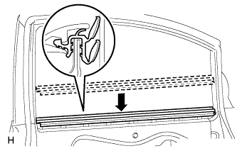
Install the front door inner glass weatherstrip.
-
-
INSTALL FRONT DOOR INSIDE HANDLE SUB-ASSEMBLY LH
-
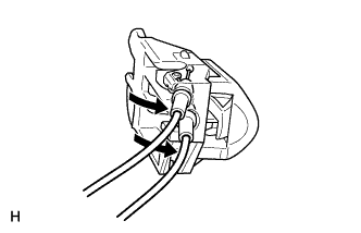
Connect the front door lock remote control cable and front door inside locking cable to the front door inside handle sub-assembly to install the inside handle.
-
-
INSTALL FRONT DOOR TRIM BOARD SUB-ASSEMBLY LH
-
Attach the 2 claws to install the front door inside handle sub-assembly to the door trim board.
-
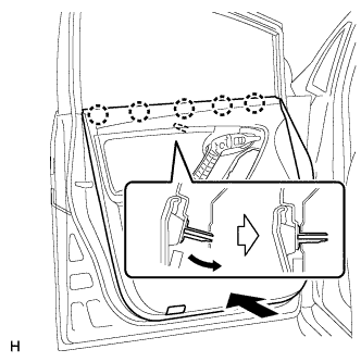
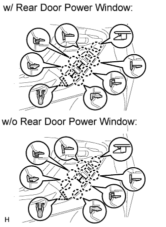
Attach the front door trim board with the 5 claws of the front door inner glass weatherstrip and the reference boss.
-
w/ Courtesy Light:
-
Connect the courtesy light connector.
-
-
Attach the 9 clips to install the trim board.
-
Install the 3 screws.
-
-
INSTALL POWER WINDOW REGULATOR MASTER SWITCH ASSEMBLY WITH FRONT DOOR ARMREST BASE PANEL
-
Connect the connector.
-
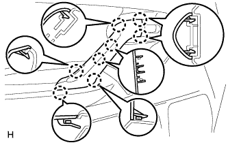
Attach the 7 claws and clip to install the power window regulator master switch assembly with front door armrest base panel.
-
-
INSTALL FRONT DOOR TRIM MOULDING LH
-
Attach the 8 claws to install the front door trim moulding.
-
-
INSTALL FRONT DOOR INSIDE HANDLE BEZEL LH
-
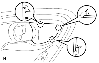
Attach the 3 claws to install the inside handle bezel.
-
-
CONNECT CABLE TO NEGATIVE BATTERY TERMINAL
Note
When disconnecting the cable, some systems need to be initialized after the cable is reconnected Click here.