DESCRIPTION
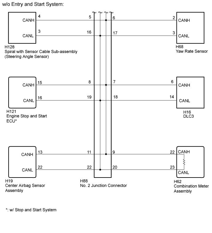
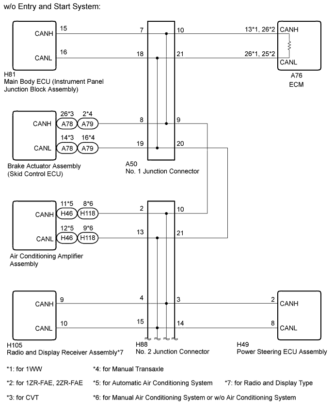
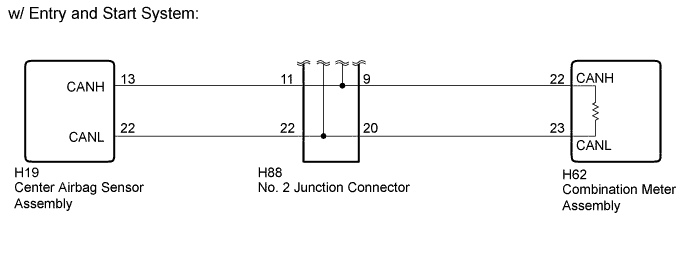
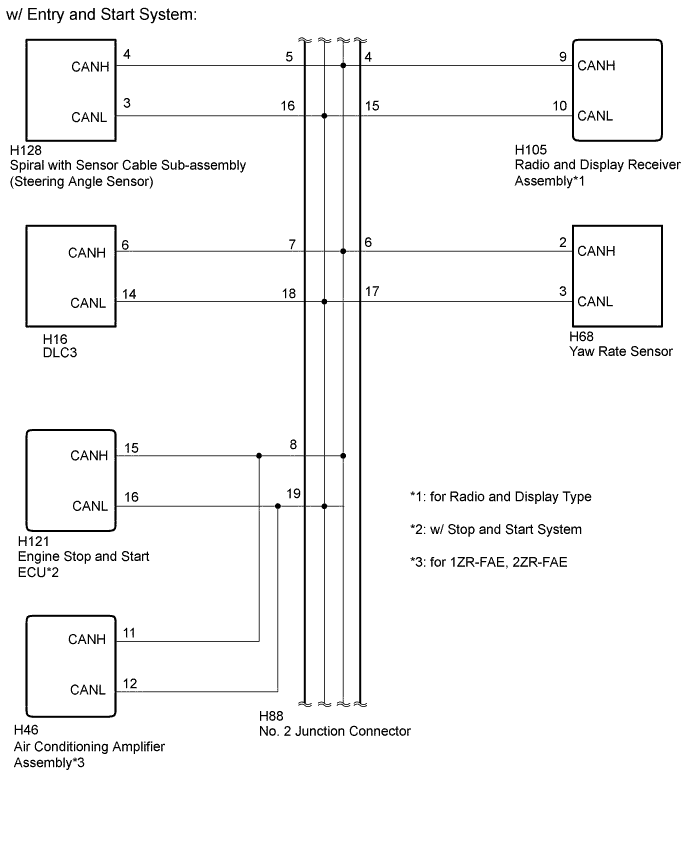
If 2 or more ECUs and/or sensors do not appear on the intelligent tester "Bus Check" screen, one side of the CAN branch wire may be open (one side of the CANH [CAN branch wire]/CANL [CAN branch wire] of the ECU and/or sensor is open).
| Symptom | Trouble Area |
|---|---|
| 2 or more ECUs and/or sensors do not appear on the intelligent tester "Bus Check" screen. |
|
-
*1: w/ Entry and Start System
-
*2: for Radio and Display Type
-
*3: w/ Stop and Start System
INSPECTION PROCEDURE
-
For vehicles with an entry and start system:
Before replacing the certification ECU (smart key ECU assembly), refer to the entry and start system (for Entry Function) (Click here).
-
After turning the ignition switch off, waiting time may be required before disconnecting the cable from the battery terminal. Therefore, make sure to read the disconnecting the cable from the battery terminal notice before proceeding with work (Click here).
-
Perform the following inspection for the ECUs (sensors) which are not displayed on the intelligent tester. If a malfunction cannot be identified, perform the following inspections for the ECUs (sensors) connected to the CAN communication system.
-
Do not remove the combination meter assembly and ECM, as they are the end parts of the circuit. If removed, CAN communication will not be possible.
-
The open circuit confirmation of the combination meter assembly, ECM and main wire is performed in the Check CAN Bus Line procedure of "How to Proceed with Troubleshooting". This inspection only has procedures for checking for an open circuit on one side of the CAN branch wire.
PROCEDURE
- Click here
CHECK FOR OPEN IN ONE SIDE OF CAN BRANCH WIRE (BRAKE ACTUATOR ASSEMBLY)
-
Disconnect the A78*1 or A79*2 brake actuator assembly (skid control ECU) connector.
-
*1: for CVT
-
*2: for Manual Transaxle
-
-
Select "Bus Check" on the intelligent tester (Click here).
Table 1. Result Result Proceed to "Skid Control (ABS/VSC/TRAC)" not displayed on the intelligent tester. A Several ECUs and sensors in addition to "Skid Control (ABS/VSC/TRAC)" not displayed on the intelligent tester. B
-
- Click here
CHECK FOR OPEN IN ONE SIDE OF CAN BRANCH WIRE (BRAKE ACTUATOR ASSEMBLY CAN BRANCH WIRE)
-
Disconnect the cable from the negative (-) battery terminal before measuring the resistances of the CAN main wire and the CAN branch wire.
CAUTION:Wait at least 90 seconds after disconnecting the cable from the negative (-) battery terminal to disable the SRS system.
Note:When disconnecting the cable, some systems need to be initialized after the cable is reconnected (Click here).
-
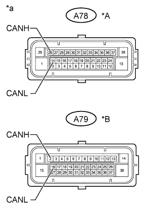
Measure the resistance according to the value(s) in the table below.
Standard Resistance Table 2. for CVT Tester Connection Switch Condition Specified Condition A78-26 (CANH) - A78-14 (CANL) Ignition switch off 54 to 69 Ω Table 3. for Manual Transaxle Tester Connection Switch Condition Specified Condition A79-2 (CANH) - A79-16 (CANL) Ignition switch off 54 to 69 Ω Table 4. Text in Illustration *A for CVT *B for Manual Transaxle *a Front view of wire harness connector
(to Brake Actuator Assembly)
- OKClick here
- NGClick here
-
- Click here
CHECK FOR OPEN IN ONE SIDE OF CAN BRANCH WIRE (ENGINE STOP AND START ECU)
Note:For vehicles without a stop and start system, go to "Check for Open in One Side of CAN Branch Wire (Main Body ECU)".
-
Disconnect the H121 engine stop and start ECU connector.
-
Select "Bus Check" on the intelligent tester (Click here).
Table 5. Result Result Proceed to "Stop and Go/Start" not displayed on the intelligent tester. A Several ECUs and sensors in addition to "Stop and Go/Start" not displayed on the intelligent tester. B
-
- Click here
CHECK FOR OPEN IN ONE SIDE OF CAN BRANCH WIRE (ENGINE STOP AND START ECU CAN BRANCH WIRE)
-
Disconnect the cable from the negative (-) battery terminal before measuring the resistances of the CAN main wire and the CAN branch wire.
CAUTION:Wait at least 90 seconds after disconnecting the cable from the negative (-) battery terminal to disable the SRS system.
Note:When disconnecting the cable, some systems need to be initialized after the cable is reconnected (Click here).
-
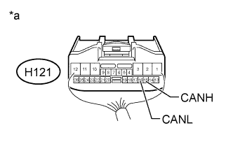
Measure the resistance according to the value(s) in the table below.
Standard Resistance Tester Connection Switch Condition Specified Condition H121-15 (CANH) - H121-16 (CANL) Ignition switch off 54 to 69 Ω Table 6. Text in Illustration *a Rear view of wire harness connector
(to Engine Stop and Start ECU)
- OKClick here
- NGClick here
-
- Click here
CHECK FOR OPEN IN ONE SIDE OF CAN BRANCH WIRE (MAIN BODY ECU)
-
Disconnect the H81 main body ECU (instrument panel junction block assembly) connector.
-
Select "Bus Check" on the intelligent tester (Click here).
Table 7. Result Result Proceed to "Main Body" not displayed on the intelligent tester. A Several ECUs and sensors in addition to "Main Body" not displayed on the intelligent tester. B
-
- Click here
CHECK FOR OPEN IN ONE SIDE OF CAN BRANCH WIRE (MAIN BODY ECU CAN BRANCH WIRE)
-
Disconnect the cable from the negative (-) battery terminal before measuring the resistances of the CAN main wire and the CAN branch wire.
CAUTION:Wait at least 90 seconds after disconnecting the cable from the negative (-) battery terminal to disable the SRS system.
Note:When disconnecting the cable, some systems need to be initialized after the cable is reconnected (Click here).
-
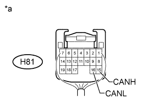
Measure the resistance according to the value(s) in the table below.
Standard Resistance Tester Connection Switch Condition Specified Condition H81-15 (CANH) - H81-16 (CANL) Ignition switch off 54 to 69 Ω Table 8. Text in Illustration *a Rear view of wire harness connector
(to Main Body ECU [Instrument Panel Junction Block Assembly])
- OKClick here
- NGClick here
-
- Click here
CHECK FOR OPEN IN ONE SIDE OF CAN BRANCH WIRE (YAW RATE SENSOR)
-
Disconnect the H68 yaw rate sensor connector.
-
Select "Bus Check" on the intelligent tester (Click here).
Table 9. Result Result Proceed to "Yaw Rate Sensor" not displayed on the intelligent tester. A Several ECUs and sensors in addition to "Yaw Rate Sensor" not displayed on the intelligent tester. B
-
- Click here
CHECK FOR OPEN IN ONE SIDE OF CAN BRANCH WIRE (YAW RATE SENSOR CAN BRANCH WIRE)
-
Disconnect the cable from the negative (-) battery terminal before measuring the resistances of the CAN main wire and the CAN branch wire.
CAUTION:Wait at least 90 seconds after disconnecting the cable from the negative (-) battery terminal to disable the SRS system.
Note:When disconnecting the cable, some systems need to be initialized after the cable is reconnected (Click here).
-
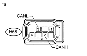
Measure the resistance according to the value(s) in the table below.
Standard Resistance Tester Connection Switch Condition Specified Condition H68-2 (CANH) - H68-3 (CANL) Ignition switch off 54 to 69 Ω Table 10. Text in Illustration *a Front view of wire harness connector
(to Yaw Rate Sensor)
- OKClick here
- NGClick here
-
- Click here
CHECK FOR OPEN IN ONE SIDE OF CAN BRANCH WIRE (SPIRAL WITH SENSOR CABLE SUB-ASSEMBLY)
-
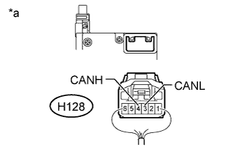
Disconnect the H128 spiral with sensor cable sub-assembly (steering angle sensor) connector.
-
Select "Bus Check" on the intelligent tester (Click here).
Table 11. Result Result Proceed to "Spiral cable (Steering Angle Sensor)" not displayed on the intelligent tester. A Several ECUs and sensors in addition to "Spiral cable (Steering Angle Sensor)" not displayed on the intelligent tester. B
-
- Click here
CHECK FOR OPEN IN ONE SIDE OF CAN BRANCH WIRE (SPIRAL WITH SENSOR CABLE SUB-ASSEMBLY CAN BRANCH WIRE)
-
Disconnect the cable from the negative (-) battery terminal before measuring the resistances of the CAN main wire and the CAN branch wire.
CAUTION:Wait at least 90 seconds after disconnecting the cable from the negative (-) battery terminal to disable the SRS system.
Note:When disconnecting the cable, some systems need to be initialized after the cable is reconnected (Click here).
-
Measure the resistance according to the value(s) in the table below.
Standard Resistance Tester Connection Switch Condition Specified Condition H128-4 (CANH) - H128-3 (CANL) Ignition switch off 54 to 69 Ω Table 12. Text in Illustration *a Rear view of wire harness connector
(to Spiral with Sensor Cable Sub-assembly)
- OKClick here
- NGClick here
-
- Click here
CHECK FOR OPEN IN ONE SIDE OF CAN BRANCH WIRE (POWER STEERING ECU ASSEMBLY)
-
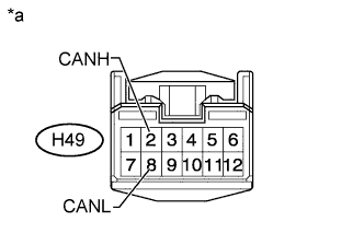
Disconnect the H49 power steering ECU assembly connector.
-
Select "Bus Check" on the intelligent tester (Click here).
Table 13. Result Result Proceed to "Power Steering (EPS)" not displayed on the intelligent tester. A Several ECUs and sensors in addition to "Power Steering (EPS)" not displayed on the intelligent tester. B
-
- Click here
CHECK FOR OPEN IN ONE SIDE OF CAN BRANCH WIRE (POWER STEERING ECU ASSEMBLY CAN BRANCH WIRE)
-
Disconnect the cable from the negative (-) battery terminal before measuring the resistances of the CAN main wire and the CAN branch wire.
CAUTION:Wait at least 90 seconds after disconnecting the cable from the negative (-) battery terminal to disable the SRS system.
Note:When disconnecting the cable, some systems need to be initialized after the cable is reconnected (Click here).
-
Measure the resistance according to the value(s) in the table below.
Standard Resistance Tester Connection Switch Condition Specified Condition H49-2 (CANH) - H49-8 (CANL) Ignition switch off 54 to 69 Ω Table 14. Text in Illustration *a Front view of wire harness connector
(to Power Steering ECU Assembly)
- OKClick here
- NGClick here
-
- Click here
CHECK FOR OPEN IN ONE SIDE OF CAN BRANCH WIRE (RADIO AND DISPLAY RECEIVER ASSEMBLY)
Note:For vehicles without a radio and display type, go to "Check for Open in One Side of CAN Branch Wire (Air Conditioning Amplifier Assembly)".
-
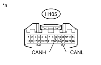
Disconnect the H105 radio and display receiver assembly connector.
-
Select "Bus Check" on the intelligent tester (Click here).
Table 15. Result Result Proceed to "Display and Navigation (AVN1)" not displayed on the intelligent tester. A Several ECUs and sensors in addition to "Display and Navigation (AVN1)" not displayed on the intelligent tester. B
-
- Click here
CHECK FOR OPEN IN ONE SIDE OF CAN BRANCH WIRE (RADIO AND DISPLAY RECEIVER ASSEMBLY CAN BRANCH WIRE)
-
Disconnect the cable from the negative (-) battery terminal before measuring the resistances of the CAN main wire and the CAN branch wire.
CAUTION:Wait at least 90 seconds after disconnecting the cable from the negative (-) battery terminal to disable the SRS system.
Note:When disconnecting the cable, some systems need to be initialized after the cable is reconnected (Click here).
-
Measure the resistance according to the value(s) in the table below.
Standard Resistance Tester Connection Switch Condition Specified Condition H105-9 (CANH) - H105-10 (CANL) Ignition switch off 54 to 69 Ω Table 16. Text in Illustration *a Front view of wire harness connector
(to Radio and Display Receiver Assembly)
- OKClick here
- NGClick here
-
- Click here
CHECK FOR OPEN IN ONE SIDE OF CAN BRANCH WIRE (AIR CONDITIONING AMPLIFIER ASSEMBLY)
Note:For vehicles with a 1WW engine type and entry and start system, go to "Check for Open in One Side of CAN Branch Wire (Certification ECU)".
-
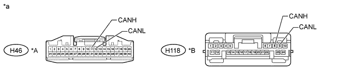
Disconnect the H46*1 or H118*2 air conditioning amplifier assembly connector.
-
*1: for Automatic Air Conditioning System
-
*2: for Manual Air Conditioning System or w/o Air Conditioning System
-
-
Select "Bus Check" on the intelligent tester (Click here).
Table 17. Result Result Proceed to "Air Conditioning Amplifier" not displayed on the intelligent tester. A Several ECUs and sensors in addition to "Air Conditioning Amplifier" not displayed on the intelligent tester. B
-
- Click here
CHECK FOR OPEN IN ONE SIDE OF CAN BRANCH WIRE (AIR CONDITIONING AMPLIFIER ASSEMBLY CAN BRANCH WIRE)
-
Disconnect the cable from the negative (-) battery terminal before measuring the resistances of the CAN main wire and the CAN branch wire.
Table 18. Text in Illustration *A for Automatic Air Conditioning System *B for Manual Air Conditioning System or w/ o Air Conditioning System *a Front view of wire harness connector
(to Air Conditioning Amplifier Assembly)
- - CAUTION:Wait at least 90 seconds after disconnecting the cable from the negative (-) battery terminal to disable the SRS system.
Note:When disconnecting the cable, some systems need to be initialized after the cable is reconnected (Click here).
-
Measure the resistance according to the value(s) in the table below.
Standard Resistance for Automatic Air Conditioning System Tester Connection Switch Condition Specified Condition H46-11 (CANH) - H46-12 (CANL) Ignition switch off 54 to 69 Ω for Manual Air Conditioning System or w/o Air Conditioning System Tester Connection Switch Condition Specified Condition H118-8 (CANH) - H118-9 (CANL) Ignition switch off 54 to 69 Ω
- OKClick here
- NGClick here
-
- Click here
CHECK FOR OPEN IN ONE SIDE OF CAN BRANCH WIRE (CERTIFICATION ECU)
Note:For vehicles without an entry and start system, go to "Check for Open in One Side of CAN Branch Wire (Power Management Control ECU)".
-
Disconnect the H51 certification ECU (smart key ECU assembly) connector.
-
Select "Bus Check" on the intelligent tester (Click here).
Table 19. Result Result Proceed to "Certification (Smart)" not displayed on the intelligent tester. A Several ECUs and sensors in addition to "Certification (Smart)" not displayed on the intelligent tester. B
-
- Click here
CHECK FOR OPEN IN ONE SIDE OF CAN BRANCH WIRE (CERTIFICATION ECU CAN BRANCH WIRE)
-
Disconnect the cable from the negative (-) battery terminal before measuring the resistances of the CAN main wire and the CAN branch wire.
CAUTION:Wait at least 90 seconds after disconnecting the cable from the negative (-) battery terminal to disable the SRS system.
Note:When disconnecting the cable, some systems need to be initialized after the cable is reconnected (Click here).
-
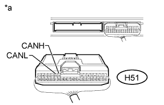
Measure the resistance according to the value(s) in the table below.
Standard Resistance Tester Connection Switch Condition Specified Condition H51-9 (CANH) - H51-10 (CANL) Ignition switch off 54 to 69 Ω Table 20. Text in Illustration *a Rear view of wire harness connector
(to Certification ECU [Smart Key ECU Assembly])
- OKClick here
- NGClick here
-
- Click here
CHECK FOR OPEN IN ONE SIDE OF CAN BRANCH WIRE (POWER MANAGEMENT CONTROL ECU)
Note:For vehicles without an entry and start system, go to "Check for Open in One Side of CAN Branch Wire (Center Airbag Sensor Assembly CAN Branch Wire)".
-
Disconnect the H71 power management control ECU connector.
-
Select "Bus Check" on the intelligent tester (Click here).
Table 21. Result Result Proceed to "Power Management1" not displayed on the intelligent tester. A Several ECUs and sensors in addition to "Power Management1" not displayed on the intelligent tester. B
-
- Click here
CHECK FOR OPEN IN ONE SIDE OF CAN BRANCH WIRE (POWER MANAGEMENT CONTROL ECU CAN BRANCH WIRE)
-
Disconnect the cable from the negative (-) battery terminal before measuring the resistances of the CAN main wire and the CAN branch wire.
CAUTION:Wait at least 90 seconds after disconnecting the cable from the negative (-) battery terminal to disable the SRS system.
Note:When disconnecting the cable, some systems need to be initialized after the cable is reconnected (Click here).
-
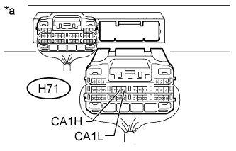
Measure the resistance according to the value(s) in the table below.
Standard Resistance Tester Connection Switch Condition Specified Condition H71-14 (CA1H) - H71-13 (CA1L) Ignition switch off 54 to 69 Ω Table 22. Text in Illustration *a Rear view of wire harness connector
(to Power Management Control ECU)
Table 23. Result Result Proceed to OK (for LHD) A OK (for RHD) B NG C
-
- Click here
CHECK FOR OPEN IN ONE SIDE OF CAN BRANCH WIRE (CENTER AIRBAG SENSOR ASSEMBLY CAN BRANCH WIRE)
-
Disconnect the cable from the negative (-) battery terminal before measuring the resistances of the CAN main wire and the CAN branch wire.
CAUTION:Wait at least 90 seconds after disconnecting the cable from the negative (-) battery terminal to disable the SRS system.
Note:When disconnecting the cable, some systems need to be initialized after the cable is reconnected (Click here).
-
Disconnect the center airbag sensor assembly connector (Click here).
-
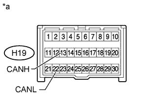
Measure the resistance according to the value(s) in the table below.
Standard Resistance Tester Connection Switch Condition Specified Condition H19-13 (CANH) - H19-22 (CANL) Ignition switch off 54 to 69 Ω Table 24. Text in Illustration *a Front view of wire harness connector
(to Center Airbag Sensor Assembly)
- OKClick here
- NGClick here
-
- Click here
REPLACE BRAKE ACTUATOR ASSEMBLY (SKID CONTROL ECU)Click here
- Click here
REPAIR OR REPLACE CAN BRANCH WIRE OR CONNECTOR (BRAKE ACTUATOR ASSEMBLY)
- Click here
REPLACE ENGINE STOP AND START ECUClick here
- Click here
REPAIR OR REPLACE CAN BRANCH WIRE OR CONNECTOR (ENGINE STOP AND START ECU)
- Click here
REPLACE MAIN BODY ECU (INSTRUMENT PANEL JUNCTION BLOCK ASSEMBLY)
- Click here
REPAIR OR REPLACE CAN BRANCH WIRE OR CONNECTOR (MAIN BODY ECU)
- Click here
REPLACE YAW RATE SENSORClick here
- Click here
REPAIR OR REPLACE CAN BRANCH WIRE OR CONNECTOR (YAW RATE SENSOR)
- Click here
ADJUST SPIRAL WITH SENSOR CABLE SUB-ASSEMBLY (STEERING ANGLE SENSOR)Click here
- Click here
REPAIR OR REPLACE CAN BRANCH WIRE OR CONNECTOR (SPIRAL WITH SENSOR CABLE SUB-ASSEMBLY)
- Click here
REPLACE POWER STEERING ECU ASSEMBLYClick here
- Click here
REPAIR OR REPLACE CAN BRANCH WIRE OR CONNECTOR (POWER STEERING ECU)
- Click here
REPLACE RADIO AND DISPLAY RECEIVER ASSEMBLYClick here
- Click here
REPAIR OR REPLACE CAN BRANCH WIRE OR CONNECTOR (RADIO AND DISPLAY RECEIVER ASSEMBLY)
- Click here
REPLACE AIR CONDITIONING AMPLIFIER ASSEMBLYClick here
- Click here
REPAIR OR REPLACE CAN BRANCH WIRE OR CONNECTOR (AIR CONDITIONING AMPLIFIER ASSEMBLY)
- Click here
REPLACE CERTIFICATION ECU (SMART KEY ECU ASSEMBLY)
- Click here
REPAIR OR REPLACE CAN BRANCH WIRE OR CONNECTOR (CERTIFICATION ECU)
- Click here
REPLACE POWER MANAGEMENT CONTROL ECUClick here
- Click here
REPLACE POWER MANAGEMENT CONTROL ECUClick here
- Click here
REPAIR OR REPLACE CAN BRANCH WIRE OR CONNECTOR (POWER MANAGEMENT CONTROL ECU)
- Click here
REPLACE CENTER AIRBAG SENSOR ASSEMBLYClick here
- Click here
REPAIR OR REPLACE CAN BRANCH WIRE OR CONNECTOR (CENTER AIRBAG SENSOR ASSEMBLY)