DESCRIPTION
There may be a short circuit between the CAN bus line and B+ when the resistance between terminals 6 (CANH) and 16 (BAT) or terminals 14 (CANL) and 16 (BAT) of the DLC3 is below 6 kΩ.
| Symptom | Trouble Area |
|---|---|
| The resistance between terminals 6 (CANH) and 16 (BAT) or terminals 14 (CANL) and 16 (BAT) of the DLC3 is below 6 kΩ. |
|
-
*1: w/ Vehicle Stability Control System
-
*2: w/o Vehicle Stability Control System
-
*3: w/ Entry and Start System
-
*4: w/o Entry and Start System
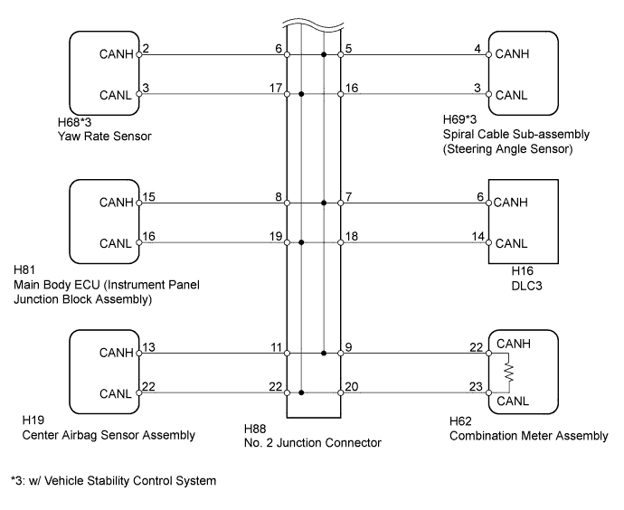
INSPECTION PROCEDURE
Operating the ignition switch, any switches or any doors triggers related ECU and sensor communication with the CAN, which causes resistance variation.
PROCEDURE
- Click here
PRECAUTION
Note:After turning the ignition switch off, waiting time may be required before disconnecting the cable from the battery terminal. Therefore, make sure to read the disconnecting the cable from the battery terminal notice before proceeding with work (Click here).
- NEXTClick here
- Click here
DISCONNECT CABLE FROM NEGATIVE BATTERY TERMINAL
-
Disconnect the cable from the negative (-) battery terminal before measuring the resistances of the CAN main wire and CAN branch wire.
CAUTION:Wait at least 90 seconds after disconnecting the cable from the negative (-) battery terminal to disable the SRS system.
Note:When disconnecting the cable, some systems need to be initialized after the cable is reconnected (Click here).
- NEXTClick here
-
- Click here
CHECK SHORT TO B+ IN CAN BUS WIRE (DLC3 BRANCH WIRE)
-
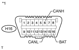
Disconnect the H88 No. 2 junction connector connector.
-
Measure the resistance according to the value(s) in the table below.
Standard Resistance Tester Connection Switch Condition Specified Condition H16-6 (CANH) - H16-16 (BAT) Ignition switch off 6 kΩ or higher H16-14 (CANL) - H16-16 (BAT) Ignition switch off 6 kΩ or higher Table 1. Text in Illustration *1 Front view of DLC3
- OKClick here
- NGClick here
-
- Click here
CONNECT CONNECTOR
-
Reconnect the H88 No. 2 junction connector connector.
- NEXTClick here
-
- Click here
CHECK SHORT TO B+ IN CAN BUS WIRE (NO. 1 JUNCTION CONNECTOR SIDE)
-
Disconnect the A50 No. 1 junction connector connector.
-
Measure the resistance according to the value(s) in the table below.
Standard Resistance Tester Connection Switch Condition Specified Condition H16-6 (CANH) - H16-16 (BAT) Ignition switch off 6 kΩ or higher H16-14 (CANL) - H16-16 (BAT) Ignition switch off 6 kΩ or higher Table 2. Text in Illustration *1 Front view of DLC3
- OKClick here
- NGClick here
-
- Click here
CHECK FOR SHORT TO B+ IN CAN BUS WIRE (NO. 1 JUNCTION CONNECTOR - BRAKE ACTUATOR)
-
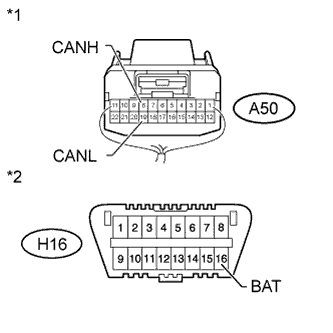
Measure the resistance according to the value(s) in the table below.
Standard Resistance Tester Connection Switch Condition Specified Condition A50-8 (CANH) - H16-16 (BAT) Ignition switch off 6 kΩ or higher A50-19 (CANL) - H16-16 (BAT) Ignition switch off 6 kΩ or higher Table 3. Text in Illustration *1 Rear view of wire harness connector
(to No. 1 Junction Connector)
*2 Front view of DLC3
- OKClick here
- NGClick here
-
- Click here
CHECK FOR SHORT TO B+ IN CAN BUS WIRE (NO. 1 JUNCTION CONNECTOR - ECM)
-
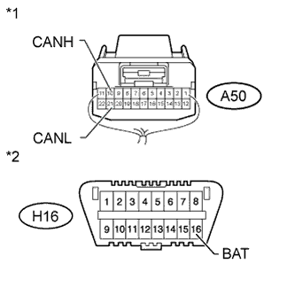
Measure the resistance according to the value(s) in the table below.
Standard Resistance Tester Connection Switch Condition Specified Condition A50-10 (CANH) - H16-16 (BAT) Ignition switch off 6 kΩ or higher A50-21 (CANL) - H16-16 (BAT) Ignition switch off 6 kΩ or higher Table 4. Text in Illustration *1 Rear view of wire harness connector
(to No. 1 Junction Connector)
*2 Front view of DLC3
- OKClick here
- NGClick here
-
- Click here
CHECK FOR SHORT TO B+ IN CAN BUS WIRE (NO. 1 JUNCTION CONNECTOR - BRAKE ACTUATOR)
-
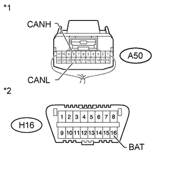
Disconnect the A53*1 brake actuator assembly (ABS ECU) or A52*2 or A54*3 brake actuator assembly (VSC ECU) connector.
-
*1: w/o Vehicle Stability Control System
-
*2: w/ Vehicle Stability Control System (for AD Series Engine)
-
*3: w/ Vehicle Stability Control System (for ZR Series Engine)
-
-
Measure the resistance according to the value(s) in the table below.
Standard Resistance Tester Connection Switch Condition Specified Condition A50-8 (CANH) - H16-16 (BATT) Ignition switch off 6 kΩ or higher A50-19 (CANL) - H16-16 (BATT) Ignition switch off 6 kΩ or higher Table 5. Text in Illustration *1 Rear view of wire harness connector
(to No. 1 Junction Connector)
*2 Front view of DLC3 Table 6. Result Result Proceed to OK (w/ Vehicle Stability Control System) A OK (w/o Vehicle Stability Control System) B NG C
-
- Click here
CHECK SHORT TO B+ IN CAN BUS WIRE (ECM)
-
Disconnect the A51 ECM connector.
-
Measure the resistance according to the value(s) in the table below.
Standard Resistance Tester Connection Switch Condition Specified Condition A50-10 (CANH) - H16-16 (BAT) Ignition switch off 6 kΩ or higher A50-21 (CANL) - H16-16 (BAT) Ignition switch off 6 kΩ or higher Table 7. Text in Illustration *1 Rear view of wire harness connector
(to No. 1 Junction Connector)
*2 Front view of DLC3 Table 8. Result Result Proceed to OK (for 1AD-FTV) A OK (for 2AD-FHV) B OK (for 1ZR-FAE) C OK (for 2ZR-FAE) D NG E
-
- Click here
CHECK FOR SHORT TO B+ IN CAN BUS WIRE (NO. 1 JUNCTION CONNECTOR - NO. 2 JUNCTION CONNECTOR)
-
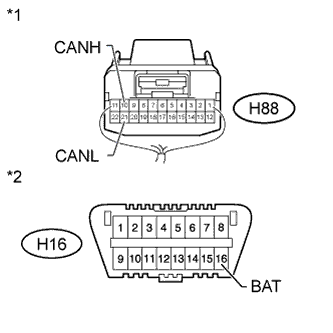
Disconnect the H88 No. 2 junction connector connector.
-
Measure the resistance according to the value(s) in the table below.
Standard Resistance Tester Connection Switch Condition Specified Condition H88-10 (CANH) - H16-16 (BATT) Ignition switch off 6 kΩ or higher H88-21 (CANL) - H16-16 (BATT) Ignition switch off 6 kΩ or higher Table 9. Text in Illustration *1 Rear view of wire harness connector
(to No. 2 Junction Connector)
*2 Front view of DLC3
- OKClick here
- NGClick here
-
- Click here
CONNECT CONNECTOR
-
Reconnect the A50 No. 1 junction connector connector.
- NEXTClick here
-
- Click here
CHECK FOR SHORT TO B+ IN CAN BUS WIRE (NO. 2 JUNCTION CONNECTOR - POWER MANAGEMENT CONTROL ECU)
Note:For vehicles without an entry and start system, go to "Check for Short in CAN Bus Wires (No. 2 Junction Connector - Air Conditioning Amplifier)".
-
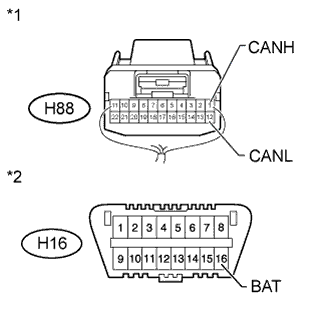
Measure the resistance according to the value(s) in the table below.
Standard Resistance Tester Connection Switch Condition Specified Condition H88-1 (CANH) - H16-16 (BAT) Ignition switch off 6 kΩ or higher H88-12 (CANL) - H16-16 (BAT) Ignition switch off 6 kΩ or higher Table 10. Text in Illustration *1 Rear view of wire harness connector
(to No. 2 Junction Connector)
*2 Front view of DLC3
- OKClick here
- NGClick here
-
- Click here
CHECK SHORT TO B+ IN CAN BUS WIRE (NO. 2 JUNCTION CONNECTOR - CERTIFICATION ECU)
-
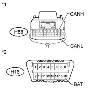
Measure the resistance according to the value(s) in the table below.
Standard Resistance Tester Connection Switch Condition Specified Condition H88-2 (CANH) - H16-16 (BAT) Ignition switch off 6 kΩ or higher H88-13 (CANL) - H16-16 (BAT) Ignition switch off 6 kΩ or higher Table 11. Text in Illustration *1 Rear view of wire harness connector
(to No. 2 Junction Connector)
*2 Front view of DLC3
- OKClick here
- NGClick here
-
- Click here
CHECK FOR SHORT TO B+ IN CAN BUS WIRE (NO. 2 JUNCTION CONNECTOR - AIR CONDITIONING AMPLIFIER)
Note:For vehicles with an entry and start system, go to "Check for Short in CAN Bus Wires (No. 2 Junction Connector - Power Steering ECU)".
-

Measure the resistance according to the value(s) in the table below.
Standard Resistance Tester Connection Switch Condition Specified Condition H88-4 (CANH) - H16-16 (BAT) Ignition switch off 6 kΩ or higher H88-15 (CANL) - H16-16 (BAT) Ignition switch off 6 kΩ or higher Table 12. Text in Illustration *1 Rear view of wire harness connector
(to No. 2 Junction Connector)
*2 Front view of DLC3
- OKClick here
- NGClick here
-
- Click here
CHECK FOR SHORT TO B+ IN CAN BUS WIRE (NO. 2 JUNCTION CONNECTOR - POWER STEERING ECU)
-
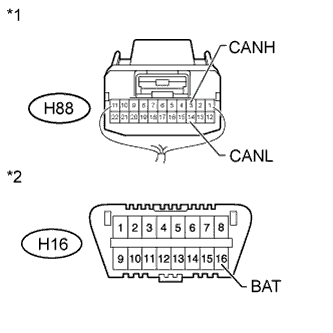
Measure the resistance according to the value(s) in the table below.
Standard Resistance Tester Connection Switch Condition Specified Condition H88-3 (CANH) - H16-16 (BAT) Ignition switch off 6 kΩ or higher H88-14 (CANL) - H16-16 (BAT) Ignition switch off 6 kΩ or higher Table 13. Text in Illustration *1 Rear view of wire harness connector
(to No. 2 Junction Connector)
*2 Front view of DLC3
- OKClick here
- NGClick here
-
- Click here
CHECK FOR SHORT TO B+ IN CAN BUS WIRE (NO. 2 JUNCTION CONNECTOR - SPIRAL CABLE)
Note:For vehicles without a vehicle stability control system, go to "Check for Short in CAN Bus Wires (No. 2 Junction Connector - Main Body ECU)".
-
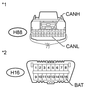
Measure the resistance according to the value(s) in the table below.
Standard Resistance Tester Connection Switch Condition Specified Condition H88-5 (CANH) - H16-16 (BAT) Ignition switch off 6 kΩ or higher H88-16 (CANL) - H16-16 (BAT) Ignition switch off 6 kΩ or higher Table 14. Text in Illustration *1 Rear view of wire harness connector
(to No. 2 Junction Connector)
*2 Front view of DLC3
- OKClick here
- NGClick here
-
- Click here
CHECK FOR SHORT TO B+ IN CAN BUS WIRE (NO. 2 JUNCTION CONNECTOR - YAW RATE SENSOR)
-
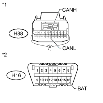
Measure the resistance according to the value(s) in the table below.
Standard Resistance Tester Connection Switch Condition Specified Condition H88-6 (CANH) - H16-16 (BAT) Ignition switch off 6 kΩ or higher H88-17 (CANL) - H16-16 (BAT) Ignition switch off 6 kΩ or higher Table 15. Text in Illustration *1 Rear view of wire harness connector
(to No. 2 Junction Connector)
*2 Front view of DLC3
- OKClick here
- NGClick here
-
- Click here
CHECK FOR SHORT TO B+ IN CAN BUS WIRE (NO. 2 JUNCTION CONNECTOR - MAIN BODY ECU)
-
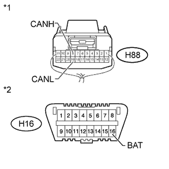
Measure the resistance according to the value(s) in the table below.
Standard Resistance Tester Connection Switch Condition Specified Condition H88-8 (CANH) - H16-16 (BAT) Ignition switch off 6 kΩ or higher H88-19 (CANL) - H16-16 (BAT) Ignition switch off 6 kΩ or higher Table 16. Text in Illustration *1 Rear view of wire harness connector
(to No. 2 Junction Connector)
*2 Front view of DLC3
- OKClick here
- NGClick here
-
- Click here
CHECK FOR SHORT TO B+ IN CAN BUS WIRE (NO. 2 JUNCTION CONNECTOR - CENTER AIRBAG SENSOR)
-
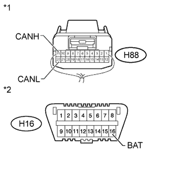
Measure the resistance according to the value(s) in the table below.
Standard Resistance Tester Connection Switch Condition Specified Condition H88-11 (CANH) - H16-16 (BAT) Ignition switch off 6 kΩ or higher H88-22 (CANL) - H16-16 (BAT) Ignition switch off 6 kΩ or higher Table 17. Text in Illustration *1 Rear view of wire harness connector
(to No. 2 Junction Connector)
*2 Front view of DLC3
- OKClick here
- NGClick here
-
- Click here
CHECK FOR SHORT TO B+ IN CAN BUS WIRE (NO. 2 JUNCTION CONNECTOR - COMBINATION METER)
-
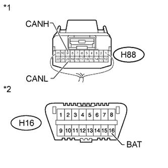
Measure the resistance according to the value(s) in the table below.
Standard Resistance Tester Connection Switch Condition Specified Condition H88-9 (CANH) - H16-16 (BAT) Ignition switch off 6 kΩ or higher H88-20 (CANL) - H16-16 (BAT) Ignition switch off 6 kΩ or higher Table 18. Text in Illustration *1 Rear view of wire harness connector
(to No. 2 Junction Connector)
*2 Front view of DLC3
- OKClick here
- NGClick here
-
- Click here
CONNECT CONNECTOR
-
Reconnect the H88 No. 2 junction connector connector.
- NEXTClick here
-
- Click here
CHECK FOR SHORT TO B+ IN CAN BUS WIRE (POWER MANAGEMENT CONTROL ECU)
-
Disconnect the H71 power management control ECU connector.
-
Measure the resistance according to the value(s) in the table below.
Standard Resistance Tester Connection Switch Condition Specified Condition H88-1 (CANH) - H16-16 (BAT) Ignition switch off 6 kΩ or higher H88-12 (CANL) - H16-16 (BAT) Ignition switch off 6 kΩ or higher Table 19. Text in Illustration *1 Rear view of wire harness connector
(to No. 2 Junction Connector)
*2 Front view of DLC3 Table 20. Result Result Proceed to OK (for LHD) A OK (for RHD) B NG C
-
- Click here
CONNECT CONNECTOR
-
Reconnect the H88 No. 2 junction connector connector.
- NEXTClick here
-
- Click here
CHECK FOR SHORT TO B+ IN CAN BUS WIRE (CERTIFICATION ECU)
-
Disconnect the H51 certification ECU connector.
-
Measure the resistance according to the value(s) in the table below.
Standard Resistance Tester Connection Switch Condition Specified Condition H88-2 (CANH) - H16-16 (BAT) Ignition switch off 6 kΩ or higher H88-13 (CANL) - H16-16 (BAT) Ignition switch off 6 kΩ or higher Table 21. Text in Illustration *1 Rear view of wire harness connector
(to No. 2 Junction Connector)
*2 Front view of DLC3
- OKClick here
- NGClick here
-
- Click here
CONNECT CONNECTOR
-
Reconnect the H88 No. 2 junction connector connector.
- NEXTClick here
-
- Click here
CHECK FOR SHORT TO B+ IN CAN BUS WIRE (AIR CONDITIONING AMPLIFIER)
-
Disconnect the H46*1 or H9*2 air conditioning amplifier assembly connector.
-
*1: for Automatic Air Conditioning System
-
*2: for Manual Air Conditioning System and w/o Air Conditioning System
-
-
Measure the resistance according to the value(s) in the table below.
Standard Resistance Tester Connection Switch Condition Specified Condition H88-4 (CANH) - H16-16 (BAT) Ignition switch off 6 kΩ or higher H88-15 (CANL) - H16-16 (BAT) Ignition switch off 6 kΩ or higher Table 22. Text in Illustration *1 Rear view of wire harness connector
(to No. 2 Junction Connector)
*2 Front view of DLC3
- OKClick here
- NGClick here
-
- Click here
CONNECT CONNECTOR
-
Reconnect the H88 No. 2 junction connector connector.
- NEXTClick here
-
- Click here
CHECK FOR SHORT TO B+ IN CAN BUS WIRE (POWER STEERING ECU)
-
Disconnect the H49 power steering ECU assembly connector.
-
Measure the resistance according to the value(s) in the table below.
Standard Resistance Tester Connection Switch Condition Specified Condition H88-3 (CANH) - H16-16 (BAT) Ignition switch off 6 kΩ or higher H88-14 (CANL) - H16-16 (BAT) Ignition switch off 6 kΩ or higher Table 23. Text in Illustration *1 Rear view of wire harness connector
(to No. 2 Junction Connector)
*2 Front view of DLC3
- OKClick here
- NGClick here
-
- Click here
CONNECT CONNECTOR
-
Reconnect the H88 No. 2 junction connector connector.
- NEXTClick here
-
- Click here
CHECK FOR SHORT TO B+ IN CAN BUS WIRE (SPIRAL CABLE)
-
Disconnect the H69 spiral cable sub-assembly (steering angle sensor) connector.
-
Measure the resistance according to the value(s) in the table below.
Standard Resistance Tester Connection Switch Condition Specified Condition H88-5 (CANH) - H16-16 (BAT) Ignition switch off 6 kΩ or higher H88-16 (CANL) - H16-16 (BAT) Ignition switch off 6 kΩ or higher Table 24. Text in Illustration *1 Rear view of wire harness connector
(to No. 2 Junction Connector)
*2 Front view of DLC3
- OKClick here
- NGClick here
-
- Click here
CONNECT CONNECTOR
-
Reconnect the H88 No. 2 junction connector connector.
- NEXTClick here
-
- Click here
CHECK FOR SHORT TO B+ IN CAN BUS WIRE (YAW RATE SENSOR)
-
Disconnect the H68 yaw rate sensor connector.
-
Measure the resistance according to the value(s) in the table below.
Standard Resistance Tester Connection Switch Condition Specified Condition H88-6 (CANH) - H16-16 (BAT) Ignition switch off 6 kΩ or higher H88-17 (CANL) - H16-16 (BAT) Ignition switch off 6 kΩ or higher Table 25. Text in Illustration *1 Rear view of wire harness connector
(to No. 2 Junction Connector)
*2 Front view of DLC3
- OKClick here
- NGClick here
-
- Click here
CONNECT CONNECTOR
-
Reconnect the H88 No. 2 junction connector connector.
- NEXTClick here
-
- Click here
CHECK FOR SHORT TO B+ IN CAN BUS WIRE (MAIN BODY ECU)
-
Disconnect the H81 main body ECU (instrument panel junction block assembly) connector.
-
Measure the resistance according to the value(s) in the table below.
Standard Resistance Tester Connection Switch Condition Specified Condition H88-8 (CANH) - H16-16 (BAT) Ignition switch off 6 kΩ or higher H88-19 (CANL) - H16-16 (BAT) Ignition switch off 6 kΩ or higher Table 26. Text in Illustration *1 Rear view of wire harness connector
(to No. 2 Junction Connector)
*2 Front view of DLC3
- OKClick here
- NGClick here
-
- Click here
CONNECT CONNECTOR
-
Reconnect the H88 No. 2 junction connector connector.
- NEXTClick here
-
- Click here
CHECK FOR SHORT TO B+ IN CAN BUS WIRE (CENTER AIRBAG SENSOR)
-
Disconnect the H19 center airbag sensor assembly connector.
-
Measure the resistance according to the value(s) in the table below.
Standard Resistance Tester Connection Switch Condition Specified Condition H88-11 (CANH) - H16-16 (BAT) Ignition switch off 6 kΩ or higher H88-22 (CANL) - H16-16 (BAT) Ignition switch off 6 kΩ or higher Table 27. Text in Illustration *1 Rear view of wire harness connector
(to No. 2 Junction Connector)
*2 Front view of DLC3
- OKClick here
- NGClick here
-
- Click here
CONNECT CONNECTOR
-
Reconnect the H88 No. 2 junction connector connector.
- NEXTClick here
-
- Click here
CHECK FOR SHORT TO B+ IN CAN BUS WIRE (COMBINATION METER)
-
Disconnect the H62 combination meter assembly connector.
-
Measure the resistance according to the value(s) in the table below.
Standard Resistance Tester Connection Switch Condition Specified Condition H88-9 (CANH) - H16-16 (BAT) Ignition switch off 6 kΩ or higher H88-20 (CANL) - H16-16 (BAT) Ignition switch off 6 kΩ or higher Table 28. Text in Illustration *1 Rear view of wire harness connector
(to No. 2 Junction Connector)
*2 Front view of DLC3
- OKClick here
- NGClick here
-
- Click here
REPLACE COMBINATION METER ASSEMBLYClick here
- Click here
REPAIR OR REPLACE CAN BRANCH WIRE CONNECTED TO DLC3 (CANH, CANL)
- Click here
REPAIR OR REPLACE NO. 1 JUNCTION CONNECTOR
- Click here
REPLACE BRAKE ACTUATOR ASSEMBLY (ABS ECU)Click here
- Click here
REPAIR OR REPLACE CAN BRANCH WIRE CONNECTED TO BRAKE ACTUATOR (CANH, CANL)
- Click here
REPLACE BRAKE ACTUATOR ASSEMBLY (VSC ECU)Click here
- Click here
REPLACE ECMClick here
- Click here
REPLACE ECMClick here
- Click here
REPLACE ECMClick here
- Click here
REPAIR OR REPLACE CAN MAIN WIRE CONNECTED TO ECM (CANH, CANL)
- Click here
REPLACE ECMClick here
- Click here
REPAIR OR REPLACE CAN MAIN WIRE OR CONNECTOR (NO. 1 JUNCTION CONNECTOR - NO. 2 JUNCTION CONNECTOR)
- Click here
REPAIR OR REPLACE NO. 2 JUNCTION CONNECTOR
- Click here
REPAIR OR REPLACE CAN BRANCH WIRE CONNECTED TO POWER MANAGEMENT CONTROL ECU (CA1H, CA1L)
- Click here
REPLACE POWER MANAGEMENT CONTROL ECUClick here
- Click here
REPAIR OR REPLACE CAN BRANCH WIRE CONNECTED TO CERTIFICATION ECU (CANH, CANL)
- Click here
REPLACE CERTIFICATION ECU
- Click here
REPAIR OR REPLACE CAN BRANCH WIRE CONNECTED TO AIR CONDITIONING AMPLIFIER (CANH, CANL)
- Click here
REPLACE AIR CONDITIONING AMPLIFIER ASSEMBLYClick here
- Click here
REPAIR OR REPLACE CAN BRANCH WIRE CONNECTED TO POWER STEERING ECU (CANH, CANL)
- Click here
REPLACE POWER STEERING ECU ASSEMBLYClick here
- Click here
REPAIR OR REPLACE CAN BRANCH WIRE CONNECTED TO SPIRAL CABLE (CANH, CANL)
- Click here
REPLACE SPIRAL CABLE SUB-ASSEMBLYClick here
- Click here
REPAIR OR REPLACE CAN BRANCH WIRE CONNECTED TO YAW RATE SENSOR (CANH, CANL)
- Click here
REPLACE YAW RATE SENSORClick here
- Click here
REPAIR OR REPLACE CAN BRANCH WIRE CONNECTED TO MAIN BODY ECU (CANH, CANL)
- Click here
REPLACE MAIN BODY ECU (INSTRUMENT PANEL JUNCTION BLOCK ASSEMBLY)
- Click here
REPLACE CENTER AIRBAG SENSOR ASSEMBLYClick here
- Click here
REPAIR OR REPLACE CAN BRANCH WIRE CONNECTED TO CENTER AIRBAG SENSOR (CANH, CANL)
- Click here
REPAIR OR REPLACE CAN MAIN WIRE CONNECTED TO COMBINATION METER (CANH, CANL)
- Click here
REPLACE POWER MANAGEMENT CONTROL ECUClick here