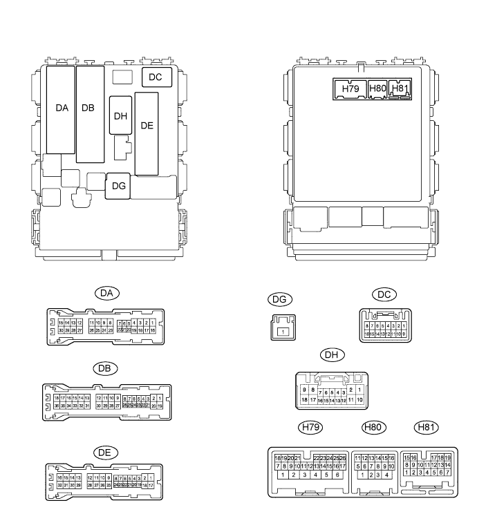
POWER DOOR LOCK CONTROL SYSTEM TERMINALS OF ECU

-
CHECK POWER WINDOW REGULATOR MASTER SWITCH ASSEMBLY

Text in Illustration *1 for LHD *2 for RHD
-
Disconnect the K5*1 or J5*2 switch connector.
*1: for LHD
*2: for RHD
-
Measure the voltage and resistance according to the value(s) in the table below.
for LHD Terminal No. (Symbol) Wiring Color Terminal Description Condition Specified Condition K5-12 (GND) - Body ground W-B - Body ground Ground Always Below 1 Ω K5-11 (B) - Body ground R - Body ground Battery power supply Always 11 to 14 V for RHD Terminal No. (Symbol) Wiring Color Terminal Description Condition Specified Condition J5-12 (GND) - Body ground W-B - Body ground Ground Always Below 1 Ω J5-11 (B) - Body ground R - Body ground Battery power supply Always 11 to 14 V If the result is not as specified, there may be a malfunction on the wire harness side.
-
-
CHECK MAIN BODY ECU (INSTRUMENT PANEL JUNCTION BLOCK ASSEMBLY)
-
Disconnect the H79, H80, DB, DE and DG ECU connectors.
-
Measure the voltage and resistance according to the value(s) in the table below.
Terminal No. (Symbol) Wiring Color Terminal Description Condition Specified Condition H79-4 (BATB) - Body ground BR - Body ground Battery power supply Always 11 to 14 V DG-1 (ALTB) - Body ground W - Body ground Battery power supply Always 11 to 14 V DB-30 (BECU) - Body ground W - Body ground Power supply Always 11 to 14 V DE-28 (GND1) - Body ground W-B - Body ground Ground Always Below 1 Ω H80-4 (GND2) - Body ground W-B - Body ground Ground Always Below 1 Ω If the result is not as specified, there may be a malfunction on the wire harness side.
-
Reconnect the H79, H80, DB, DE and DG ECU connectors.
-
Measure the voltage according to the value(s) in the table below.
for LHD Terminal No. (Symbol) Wiring Color Terminal Description Condition Specified Condition DA-21 (DCTY) - Body ground W - Body ground Front door courtesy light switch LH input Driver side door open Below 1 V DA-21 (DCTY) - Body ground W - Body ground Front door courtesy light switch LH input Driver side door closed 11 to 14 V DE-20 (PCTY) - Body ground BR - Body ground Front door courtesy light switch RH input Front passenger side door open Below 1 V DE-20 (PCTY) - Body ground BR - Body ground Front door courtesy light switch RH input Front passenger side door closed 11 to 14 V H79-8 (LCTY) - Body ground SB - Body ground Rear door courtesy light switch LH input Rear door LH open Below 1 V H79-8 (LCTY) - Body ground SB - Body ground Rear door courtesy light switch LH input Rear door LH closed 11 to 14 V DE-19 (RCTY) - Body ground LG - Body ground Rear door courtesy light switch RH input Rear door RH open Below 1 V DE-19 (RCTY) - Body ground LG - Body ground Rear door courtesy light switch RH input Rear door RH closed 11 to 14 V DA-7 (BCTY) - Body ground LG - Body ground Back door courtesy light switch input Back door open Below 1 V DA-7 (BCTY) - Body ground LG - Body ground Back door courtesy light switch input Back door closed 11 to 14 V DH-8 (ACT+) - Body ground BE - Body ground Front door lock LH (door lock motor) lock drive output Master switch (door control switch) or front door lock key cylinder neutral position Below 1 V DH-8 (ACT+) - Body ground BE - Body ground Front door lock LH (door lock motor) lock drive output Master switch (door control switch) or front door lock key cylinder lock 11 to 14 V DH-17 (ACT+) - Body ground R - Body ground Front door lock RH (door lock motor), rear door lock RH (door lock motor) lock drive output Master switch (door control switch) or front door lock key cylinder neutral position Below 1 V DH-17 (ACT+) - Body ground R - Body ground Front door lock RH (door lock motor), rear door lock RH (door lock motor) lock drive output Master switch (door control switch) or front door lock key cylinder lock 11 to 14 V DA-3 (ACT+) - Body ground R - Body ground Rear door lock LH (door lock motor) lock drive output Master switch (door control switch) or front door lock key cylinder neutral position Below 1 V DA-3 (ACT+) - Body ground R - Body ground Rear door lock LH (door lock motor) lock drive output Master switch (door control switch) or front door lock key cylinder lock 11 to 14 V DH-9 (ACT-) - Body ground LG - Body ground Front door lock LH (door lock motor) unlock drive output Master switch (door control switch) or front door lock key cylinder neutral position Below 1 V DH-9 (ACT-) - Body ground LG - Body ground Front door lock LH (door lock motor) unlock drive output Master switch (door control switch) or front door lock key cylinder unlock 11 to 14 V DA-4 (ACT-) - Body ground SB - Body ground Rear door lock LH (door lock motor) unlock drive output Master switch (door control switch) or front door lock key cylinder neutral position Below 1 V DA-4 (ACT-) - Body ground SB - Body ground Rear door lock LH (door lock motor) unlock drive output Master switch (door control switch) or front door lock key cylinder unlock 11 to 14 V DH-18 (ACT-) - Body ground SB - Body ground Front door lock RH (door lock motor), rear door lock RH (door lock motor) unlock drive output Master switch (door control switch) or front door lock key cylinder neutral position Below 1 V DH-18 (ACT-) - Body ground SB - Body ground Front door lock RH (door lock motor), rear door lock RH (door lock motor) unlock drive output Master switch (door control switch) or front door lock key cylinder unlock 11 to 14 V DH-7 (L2) - Body ground SB - Body ground Front door lock LH key switch input Front door lock key cylinder lock Below 1 V DH-7 (L2) - Body ground SB - Body ground Front door lock LH key switch input Ignition switch off, all doors closed and front door lock key cylinder neutral position Pulse generation (see waveform 1 or 2) H79-1 (TR+) - Body ground R - Body ground Back door lock unlock motor drive output Master switch (door control switch) or front door lock key cylinder neutral position Below 1 V H79-1 (TR+) - Body ground R - Body ground Back door lock unlock motor drive output Master switch (door control switch) or front door lock key cylinder unlock 11 to 14 V H79-25 (LSWD) - Body ground Y - Body ground Front door lock LH (door lock position switch) input Driver side door unlocked Below 1 V H79-25 (LSWD) - Body ground Y - Body ground Front door lock LH (door lock position switch) input Ignition switch off, all doors closed and driver side door locked Pulse generation (see waveform 3 or 4) H79-10 (LSWP) - Body ground LG - Body ground Front door lock RH (door lock position switch) input Front passenger side door unlocked Below 1 V H79-10 (LSWP) - Body ground LG - Body ground Front door lock RH (door lock position switch) input Ignition switch off, all doors closed and front passenger side door locked Pulse generation (see waveform 5 or 6) H81-10 (LSR) - Body ground Y - Body ground Rear door lock (door lock position switch) input Rear door unlocked Below 1 V H81-10 (LSR) - Body ground Y - Body ground Rear door lock (door lock position switch) input Ignition switch off, all doors closed and rear door locked Pulse generation (see waveform 7 or 8) H79-12 (BDSU) - Body ground* V - Body ground Back door opener switch input Back door opener switch off Below 1 V H79-12 (BDSU) - Body ground* V - Body ground Back door opener switch input Ignition switch off, all doors closed and back door opener switch on Pulse generation (see waveform 9 or 10) DH-6 (UL2) - Body ground P - Body ground Front door lock LH (key-linked switch) input Front door lock key cylinder lock Below 1 V DH-6 (UL2) - Body ground P - Body ground Front door lock LH (key-linked switch) input Ignition switch off, all doors closed and front door lock key cylinder neutral position Pulse generation (see waveform 11 or 12)
-
*: w/o Entry and Start System
for RHD Terminal No. (Symbol) Wiring Color Terminal Description Condition Specified Condition DC-6 (DCTY) - Body ground BR - Body ground Front door courtesy light switch RH input Driver side door open Below 1 V DC-6 (DCTY) - Body ground BR - Body ground Front door courtesy light switch RH input Ignition switch off and front door courtesy light switch RH off 11 to 14 V DA-24 (PCTY) - Body ground W - Body ground Front door courtesy light switch LH input Front passenger side door open Below 1 V DA-24 (PCTY) - Body ground W - Body ground Front door courtesy light switch LH input Ignition switch off and front door courtesy light switch LH off 11 to 14 V H79-8 (LCTY) - Body ground SB - Body ground Rear door courtesy light switch LH input Rear door LH open Below 1 V H79-8 (LCTY) - Body ground SB - Body ground Rear door courtesy light switch LH input Ignition switch off and rear door courtesy light switch LH off 11 to 14 V DE-19 (RCTY) - Body ground LG - Body ground Rear door courtesy light switch RH input Rear door RH open Below 1 V DE-19 (RCTY) - Body ground LG - Body ground Rear door courtesy light switch RH input Ignition switch off and rear door courtesy light switch RH off 11 to 14 V DA-7 (BCTY) - Body ground LG - Body ground Back door courtesy light switch input Back door open Below 1 V DA-7 (BCTY) - Body ground LG - Body ground Back door courtesy light switch input Ignition switch off and back door closed 11 to 14 V DH-8 (ACT+) - Body ground BE - Body ground Front door lock LH (door lock motor) lock drive output Master switch (door control switch) or front door lock key cylinder neutral position Below 1 V DH-8 (ACT+) - Body ground BE - Body ground Front door lock LH (door lock motor) lock drive output Master switch (door control switch) or front door lock key cylinder lock 11 to 14 V DH-17 (ACT+) - Body ground R - Body ground Front door lock RH (door lock motor), rear door lock RH (door lock motor) lock drive output Master switch (door control switch) or front door lock key cylinder neutral position Below 1 V DH-17 (ACT+) - Body ground R - Body ground Front door lock RH (door lock motor), rear door lock RH (door lock motor) lock drive output Master switch (door control switch) or front door lock key cylinder lock 11 to 14 V DA-3 (ACT+) - Body ground R - Body ground Rear door lock LH (door lock motor) lock drive output Master switch (door control switch) or front door lock key cylinder neutral position Below 1 V DA-3 (ACT+) - Body ground R - Body ground Rear door lock LH (door lock motor) lock drive output Master switch (door control switch) or front door lock key cylinder lock 11 to 14 V DH-9 (ACT-) - Body ground LG - Body ground Front door lock LH (door lock motor) unlock drive output Master switch (door control switch) or front door lock key cylinder neutral position Below 1 V DH-9 (ACT-) - Body ground LG - Body ground Front door lock LH (door lock motor) unlock drive output Master switch (door control switch) or front door lock key cylinder unlock 11 to 14 V DA-4 (ACT-) - Body ground SB - Body ground Rear door lock LH (door lock motor) unlock drive output Master switch (door control switch) or front door lock key cylinder neutral position Below 1 V DA-4 (ACT-) - Body ground SB - Body ground Rear door lock LH (door lock motor) unlock drive output Master switch (door control switch) or front door lock key cylinder unlock 11 to 14 V DH-18 (ACT-) - Body ground SB - Body ground Front door lock RH (door lock motor), rear door lock RH (door lock motor) unlock drive output Master switch (door control switch) or front door lock key cylinder neutral position Below 1 V DH-18 (ACT-) - Body ground SB - Body ground Front door lock RH (door lock motor), rear door lock RH (door lock motor) unlock drive output Master switch (door control switch) or front door lock key cylinder unlock 11 to 14 V DH-7 (L2) - Body ground SB - Body ground Front door lock RH key switch input Front door lock key cylinder lock Below 1 V DH-7 (L2) - Body ground SB - Body ground Front door lock RH key switch input Ignition switch off, all doors closed and front door lock key cylinder neutral position Pulse generation (see waveform 1 or 2) H79-1 (TR+) - Body ground R - Body ground Back door lock unlock motor drive output Master switch (door control switch) or front door lock key cylinder neutral position Below 1 V H79-1 (TR+) - Body ground R - Body ground Back door lock unlock motor drive output Master switch (door control switch) or front door lock key cylinder unlock 11 to 14 V H79-25 (LSWD) - Body ground LG - Body ground Front door lock RH (door lock position switch) input Driver side door unlocked Below 1 V H79-25 (LSWD) - Body ground LG - Body ground Front door lock RH (door lock position switch) input Ignition switch off, all doors closed and driver side door locked Pulse generation (see waveform 3 or 4) H79-10 (LSWP) - Body ground LG - Body ground Front door lock LH (door lock position switch) input Front passenger side door unlocked Below 1 V H79-10 (LSWP) - Body ground LG - Body ground Front door lock LH (door lock position switch) input Ignition switch off, all doors closed and front passenger side door locked Pulse generation (see waveform 5 or 6) H81-10 (LSR) - Body ground Y - Body ground Rear door lock (door lock position switch) input Rear door unlocked Below 1 V H81-10 (LSR) - Body ground Y - Body ground Rear door lock (door lock position switch) input Ignition switch off, all doors closed and rear door locked Pulse generation (see waveform 7 or 8) H79-12 (BDSU) - Body ground* V - Body ground Back door opener switch input Back door opener switch off Below 1 V H79-12 (BDSU) - Body ground* V - Body ground Back door opener switch input Ignition switch off, all doors closed and back door opener switch on Pulse generation (see waveform 9 or 10) DH-6 (UL2) - Body ground P - Body ground Front door lock RH (key-linked switch) input Front door lock key cylinder lock Below 1 V DH-6 (UL2) - Body ground P - Body ground Front door lock RH (key-linked switch) input Ignition switch off, all doors closed and front door lock key cylinder neutral position Pulse generation (see waveform 11 or 12)
-
*: w/o Entry and Start System
If the result is not as specified, the ECU may have a malfunction.
-
-
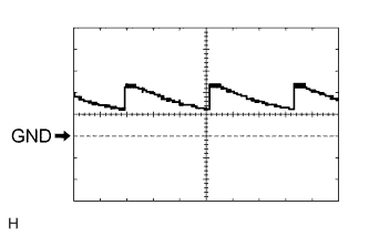
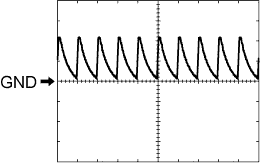
Using an oscilloscope, check waveform 1.
Waveform 1 (Reference) Item Content Terminal No. (Symbol) DH-7 (L2) - Body ground Tool Setting 5 V/DIV., 20 ms/DIV. Condition Ignition switch off, all doors closed and front door lock key cylinder neutral position -
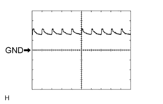
Using an oscilloscope, check waveform 2.
Waveform 2 (Reference) Item Content Terminal No. (Symbol) DH-7 (L2) - Body ground Tool Setting 5 V/DIV., 20 ms/DIV. Condition Ignition switch off, all doors closed and front door lock key cylinder neutral position -
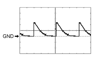
Using an oscilloscope, check waveform 3.
Waveform 3 (Reference) Item Content Terminal No. (Symbol) H79-25 (LSWD) - Body ground Tool Setting 5 V/DIV., 20 ms/DIV. Condition Ignition switch off, all doors closed and driver side door locked -
Using an oscilloscope, check waveform 4.
Waveform 4 (Reference) Item Content Terminal No. (Symbol) H79-25 (LSWD) - Body ground Tool Setting 5 V/DIV., 20 ms/DIV. Condition Ignition switch off, all doors closed and driver side door locked -
Using an oscilloscope, check waveform 5.
Waveform 5 (Reference) Item Content Terminal No. (Symbol) H79-10 (LSWP) - Body ground Tool Setting 5 V/DIV., 20 ms/DIV. Condition Ignition switch off, all doors closed and front passenger side door locked -
Using an oscilloscope, check waveform 6.
Waveform 6 (Reference) Item Content Terminal No. (Symbol) H79-10 (LSWP) - Body ground Tool Setting 5 V/DIV., 20 ms/DIV. Condition Ignition switch off, all doors closed and front passenger side door locked -
Using an oscilloscope, check waveform 7.
Waveform 7 (Reference) Item Content Terminal No. (Symbol) H81-10 (LSR) - Body ground Tool Setting 5 V/DIV., 20 ms/DIV. Condition Ignition switch off, all doors closed and rear door locked -
Using an oscilloscope, check waveform 8.
Waveform 8 (Reference) Item Content Terminal No. (Symbol) H81-10 (LSR) - Body ground Tool Setting 5 V/DIV., 20 ms/DIV. Condition Ignition switch off, all doors closed and rear door locked -
Using an oscilloscope, check waveform 9.
Waveform 9 (Reference) Item Content Terminal No. (Symbol) H79-12 (BDSU) - Body ground Tool Setting 5 V/DIV., 20 ms/DIV. Condition Ignition switch off, all doors closed and back door opener switch on -
Using an oscilloscope, check waveform 10.
Waveform 10 (Reference) Item Content Terminal No. (Symbol) H79-12 (BDSU) - Body ground Tool Setting 5 V/DIV., 20 ms/DIV. Condition Ignition switch off, all doors closed and back door opener switch on -
Using an oscilloscope, check waveform 11.
Waveform 11 (Reference) Item Content Terminal No. (Symbol) DH-6 (UL2) - Body ground Tool Setting 5 V/DIV., 20 ms/DIV. Condition Ignition switch off, all doors closed and driver side key cylinder neutral position -
Using an oscilloscope, check waveform 12.
Waveform 12 (Reference) Item Content Terminal No. (Symbol) DH-6 (UL2) - Body ground Tool Setting 5 V/DIV., 20 ms/DIV. Condition Ignition switch off, all doors closed and driver side key cylinder neutral position
-
-
CHECK DOUBLE LOCK DOOR CONTROL RELAY (w/ Double Locking System)

-
Disconnect the H50 relay connector.
-
Measure the voltage and resistance according to the value(s) in the table below.
Terminal No. (Symbol) Wiring Color Terminal Description Condition Specified Condition H50-14 (GND) - Body ground W-B - Body ground Ground Always Below 1 Ω H50-1 (+B) - Body ground B - Body ground Battery power supply Always 11 to 14 V H50-7 (CPUB) - Body ground W - Body ground Battery power supply Always 11 to 14 V If the result is not as specified, there may be a malfunction on the wire harness side.
-
Reconnect the H50 relay connector.
-
Measure the voltage and resistance according to the value(s) in the table below.
Terminal No. (Symbol) Wiring Color Terminal Description Condition Specified Condition H50-6 (DLPP) - Body ground R - Body ground Front door lock LH (double door lock position switch) input Double lock not set 10 kΩ or higher H50-6 (DLPP) - Body ground R - Body ground Front door lock LH (double door lock position switch) input Double lock set Below 1 Ω H50-5 (DLPD) - Body ground GR - Body ground Front door lock RH (double door lock position switch) input Double lock not set 10 kΩ or higher H50-5 (DLPD) - Body ground GR - Body ground Front door lock RH (double door lock position switch) input Double lock set Below 1 Ω H50-11 (DLPR) - Body ground L - Body ground Rear door lock RH (double door lock position switch) input Double lock not set 10 kΩ or higher H50-11 (DLPR) - Body ground L - Body ground Rear door lock RH (double door lock position switch) input Double lock set Below 1 Ω H50-12 (DLPL) - Body ground P - Body ground Rear door lock LH (double door lock position switch) input Double lock not set 10 kΩ or higher H50-12 (DLPL) - Body ground P - Body ground Rear door lock LH (double door lock position switch) input Double lock set Below 1 Ω H50-4 (ACTR) - Body ground G - Body ground All door double lock motor set off output Double lock set → not set Below 1 V → 11 to 14 V → Below 1 V H50-3 (ACTS) - Body ground BR - Body ground All door double lock motor set on output Double lock not set → set Below 1 V → 11 to 14 V → Below 1 V If the result is not as specified, the relay may have a malfunction.
-